


Chapter 7 - Options
101
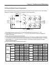
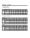
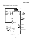
7.1.3 Braking resistor wiring diagram
Wire the braking resistor to the inverter as short as possible.
230/460V
50/60Hz
U
V
W
G
R
S
T
3 Phase
MCCB
FX
RX
BX
RST
P1
P3
CM
VR
V1
I
CM
+
FM
CM
A
B
C
Output Frequency Meter
0~10V (Analog)
P2
MOTOR
Potentiometer
(1 kohm, 1/2W)
Speed signal Input
1
Set to ‘EXT-B
Power suppl
y
for
speed signal:
+ 12V, 10mA
Speed signal input:
0 ~ 10V
Speed signal input:
4 ~20mA (250ohm)
Common for
VR, V1, I
Fault output relay
lless than AC250V, 1A
lless than DC30V, 1A
Note) 1. Analog speed command can be set by Voltage, Current and both of them.
2. DB resistor is optional.
B2B1
FM
JOG
Shield
DB Resistor
2
MODBUS-RTU Communication port
S+
S-
Thermal sensor (NC)
MO
MG
lless than DC24V, 50mA
Factory setting: ‘Run’
1 Phase
230V, or
Max. 5m between Inverter and resistor
TH1 TH2