


Chapter 4 - Parameter Description [I/O]
69
average ranges from 0V to 10V. I/O-41 is used to
adjust the FM value.
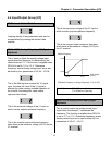
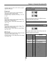
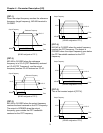
[Frequency]
FM terminal outputs inverter output frequency.
The output value is determined by,
FM Output Voltage = (Output freq. / Max. freq.) × 10V × IO-
41 / 100
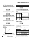
[Current]
FM terminal outputs inverter output current. The
output value is determined by,
FM Output Voltage = (Output current / Rated current) × 10V
× IO-41 / 150
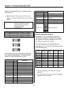
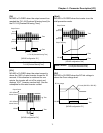
[Voltage]
FM terminal outputs inverter output voltage. The
output value is determined by,
FM Output Voltage = (Output voltage / Max. output voltage) ×
10V × IO-41 / 100
[DC link vtg]
FM terminal outputs the DC link voltage of inverter.
The output value is determined by,
FM Output Voltage = (DC link voltage / Max. DC link voltage)
× 10V × IO-41 / 100
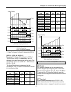
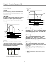
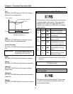
I/O-42: FDT (Frequency Detection) Level
I/O-43: FDT Bandwidth
These functions are used in I/O-44 [Multi-function
Output]. See [FDT-#] in I/O-44.
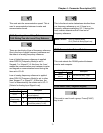
I/O-44: Multi-function Output define (MO-MG)
The open collector output works (Close) when the
defined condition has occurred.
Setting Range
Select Display
Description
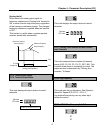
FDT-1
0
Output frequency arrival detection
FDT-2
1
Specific frequency level detection
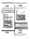
FDT-3
2
Frequency detection with pulse
FDT-4
3
Frequency detection with contact
closure
FDT-5
4
Frequency detection with contact
closure (inverted FDT-4)
OL
5
Overload detection
IOL
6
Inverter overload detection
Stall
7
Stall prevention mode detection
OV
8
Over voltage detection
LV
9
Low voltage detection
OH
10
Overheat detection
Lost Command
11
Lost command detection
Run
12
Inverter running detection
Stop
13
Inverter stop detection
Steady
14
Steady speed detection
-Reserved-
15 ~16
Reserved for future use
Ssearch
17
Speed search mode detection
-Reserved-
18 ~19
Reserved for future use
Ready
20
Inverter is ready status to run
Related Functions: I/O-44 [Multi-function Output]