


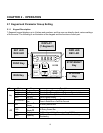

Chapter 1 - Installation
12
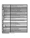
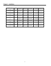
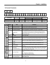
Wires and Terminal Lugs
Refer to the following table for wires, terminal lugs and screws used to connect the inverter power input
(R, S, T) and output (U, V, W).
Wire
6
Ring Terminals
mm
2
AWG
Inverter
Terminal
Screw
Size
Screw
Torque
5
(Kgf·cm)/lb-in
R,S,T U,V,W R,S,T U,V,W R,S,T U,V,W
0.5 HP M 3.5 10 / 7 2-3.5 2-3.5 2 2 14 14 200V Class
(1 Phase)
1 ~ 2 HP M 4.0 15 / 10 2-4 2-4 2 2 14 14
0.5 ~ 1 HP M 3.5 10 / 7 2-3.5 2-3.5 2 2 14 14
2 ~ 3 HP M 4.0 15 / 10 2-4 2-4 2 2 14 14
200V Class
(3 Phase)
5 ~ 5.4 HP M 4.0 15 / 10 5.5-4 5.5-4 3.5 3.5 12 12
400V Class
(3 Phase)
0.5 ~ 5.4 HP M 4.0 15 / 10 2-4 2-4 2 2 14 14
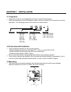
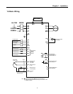
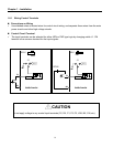
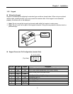
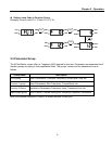
Power and Motor Connection
R S T B1 B2 U V W
5
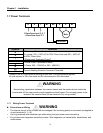
Apply the rated torque to terminal screws. Loosen screws can cause of short circuit and malfunction. Tightening the screws too much can
damage the terminals and cause short circuit and malfunction.
6
Use copper wires with 600V, 75℃ratings for wiring only.
Power supply must be connected
to the R, S, and T Terminals.
Connecting it to the U, V, W
terminals causes internal damages
to the inverter. Arranging the phase
sequence is not necessary.
Motor should be connected to the
U, V, and W Terminals.
If the forward command (FX) is on,
the motor should rotate counter
clockwise when viewed from the load
side of the motor. If the motor rotates
in the reverse, switch the U and V
terminals.
Motor
3 Phase Power Input: R, S, T
1 Phase Power Input: R, T
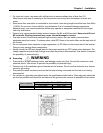
WARNING WARNING