


Chapter 1 - Installation
15
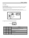
1.8.2 Keypad
Wiring the Keypad
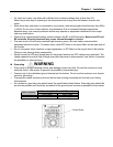
Keypad is installed before shipping for standard type models as shown below. When using an optional
remote cable, install the buffer cover and connect the remote cable. If the keypad is not connected
properly, the letters will not be displayed.
☞ Note: Do not connect the keypad and remote cable while the inverter is under power.
☞ Note: Do not touch the live part of the keypad connector. Doing this may cause an electric shock or
personal injury.
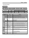
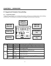
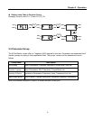
Keypad Connector Pin Configuration (Inverter Side)
Pin No. Pin Name Keypad Description
1 5V Used 5V DC Power Supply (Isolated from VR, V1, I of Control Terminal)
2 GND Used 5V DC Power Ground (Isolated from CM of Control Terminal)
3 RES Used
4 VPP Used
Used for Writing Flash ROM Inside Inverter.
5 LAT Used Latch Signal for Transmitting/Receiving
6 TXD Used Transmitting Signal Pin
7 CLK Used Clock Signal Pin
8 RXD Used Receiving Signal Pin
9 Not Used
10 Not Used
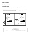
2 4 6 8 10
1 3 5 7 9
(Top View)
Keypad
(Detachable)