


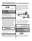


Chapter 4 - Parameter Description [FU2]
56
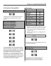
FU2-40: Control Method Selection
This is to select the control method of inverter.
Setting Range
Select Display
Description
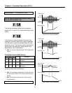
V/F
0
Volts/Hz Control
Slip compen
1
Slip compensation operation
PID
2
PID feedback operation
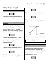
[V/F]: This parameter controls the
voltage/frequency ratio constant. It is
recommended to use the torque boost function
when a greater starting torque is required.
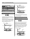
[Slip compen]: This function is used to maintain
constant motor speed. To keep the motor speed
constant, the output frequency varies within the
limit of slip frequency set in FU2-32 according to
the load current. For example, when the motor
speed decreases below the reference speed
(frequency) due to a heavy load, the inverter
increases the output frequency higher than the
reference frequency to increase the motor speed.
The inverter increases or decreases the output by
delta frequency shown below.
Output frequency = Reference freq. + Delta freq.
☞
Note: Motor parameters must be set correctly for better
performance of control.
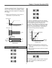
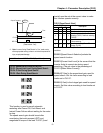
[PID]: For HVAC or Pump applications, the PID
control can be used to adjust the actual output by
comparing a feedback with a ‘Set-point’ given to
the inverter. This ‘Set-point’ can be in the form of
Speed, Temperature, Pressure, Flow level, etc.
The ‘Set-point’ and the feedback signals are
provided externally to the inverter analog input
terminals V1, V2 or I. The inverter compares the
signals in calculating ‘total-error’ which is reflected
in the inverter output.
Please see FU2-50 to FU2-54 for more detail.
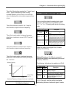
[PID Control Block Diagram]
☞
Note: PID control can be bypassed to manual operation
temporarily by defining one of the multifunction input terminals
(P1~P3) to “Open-Loop”. The inverter will change to manual
operation from PID control when this terminal is ON, and
change back to PID control when this terminal is OFF.
FU2-50: PID Feedback Signal Selection
FU2-51: P Gain for PID Control
FU2-52: I Gain for PID Control
FU2-53: D Gain for PID Control
FU2-54: Limit Frequency for PID Control
Select the feedback signal for PID control. This
can be set one of ‘I’, ‘V1’, ‘V2’ according to the
signal (current or voltage) and the terminal (V1 or
V2).
Related Functions: FU2-26 ~ FU2-28 [Torque Boost]
Related Functions: FU2-30 ~ FU2-37 [Motor Parameters]
Delta
Freq.
=
Output current – No load
Rated current – No load
Rated Slip
×
Related Functions: DRV-04 [Frequency Mode]
I/O-01 to I/O-10 [Analog Signal Setting]
I/O-12 to I/O-14 [Multi-Function Input]
FU2-50 to FU2-54 [PID Feedback]
Set-point (DRV-04)
+
-
Keypad-1
Keypad-2
V1
I
V1+I
FU2-51
FU2-52
FU2-53
M
Process
Transducer
4 to 20mA or
0 to 10 V
FU2-50
FU2-54
I/O-12
~
I/O-14
er
r
DRV-01
DRV-02
Reference
Feedback