SYSTEM MAINTENANCE
41
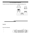
Testing the Flow Switch, Cleaning the Filter Screen, and Cleaning the Bypass Valve
The flow switch is an important safety protection device. When
water flow has stopped, it is important that the SuperCell be
automatically turned off to prevent damage to the cell or system. It
is important to verify the safe and proper operation of the Tri-
sensor’s Flow Switch protection device. The following procedure
can be used to verify the proper operation of the flow switch or to
flush debris from the Bypass Valve.
1. Turn off the pump.
2. Slightly loosen the union nut just below the cell on the side
of the manifold that does not contain the filter screen.
3. Completely loosen the manifold union nut that contains the
filter screen and pivot the manifold to gain access to the
filter screen.
4. Remove the screen. Clean the screen if dirty.
5. If the screen was dirty, then the system may need to be
purged to remove excess debris. Leave the manifold off
and run the pump for a few seconds until clear.
6. Wrap the strainer screen securely with a small piece of
plastic wrap (saran wrap, food wrap or zip lock bag) as
indicated in the diagram, place it back in the union.
7. Tighten the two unions that were loosened.
8. Reconnect the tri-sensor cord onto the tri-sensor.
9. Turn on the pump and the Pool Pilot. The plastic will stop water flow to the flow switch, which is part of the Tri-Sensor
that is located in the upper portion of the manifold. (All of the water will be forced through the Bypass Valve. This will
normally flush out any small bits of debris that are trapped in the Bypass Valve.)
10. The Control Unit should detect a low water flow at the Tri-Sensor and activate the red Check System LED. The Control
Unit will also display the message “Purifier Off! Check Flow”.
11. If the Control Unit did not display this warning, then check the Tri-Sensor cable connections and inspect and clean the
Tri-Sensor as outlined in the previous section. If the warning message still does not appear, then turn the Pool Pilot off
and contact the factory or your local dealer for assistance.
12. Turn the pump off.
13. Loosen the unions.
14. Remove the plastic wrap and replace the strainer screen.
15. Resume operation.
SuperCell
The SuperCell may require removal for periodic visual inspections or f or servicin g w hen debris o r calcium mineral deposits
develop (the Control Unit displays the “Check System” light and the message, “Low Flow, Purifier OFF” or “Check Cell / Clean
Cell”.)
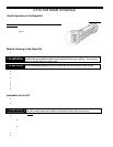
Removal of the SuperCell:
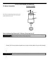
The SuperCell is installed with Unions on each end to allow quick and easy installation and removal.
• Turn off all power.
• Detach the SuperCell cable from the
SuperCell.
• Unscrew the unions at both ends of the
SuperCell.
• Slide the SuperCell out of the Manifold
Assembly.
SuperCell and Unions – (side view)


