


INSTALLATION
22
➀
②
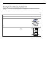
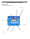
Optional Tap Points
For
Digital TC
Total Control
A
cid In
Water Out
Tap Point
Locations
A
lways Insert tubing
into appropriate
inlet/outlet.
See Digital TC manual
for drilling instructions.
Stenner
Acid Pump
and Tank
Kit
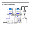
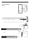
pH Control Installation
Plumbing
Have these tools on hand prior to starting this step:
• Drill
• 1/2” standard drill bit (or 1/4” NPT bit and tap if using Stenner
components)
• Utility knife
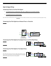
A hole must be drilled into the manifold assembly for installation of the
injector fitting for the Muriatic Acid.
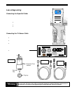
1. Locate the Acid Feed Pump and tank within proper cord
distances to the Pool Chemistry Controller System and Power source.
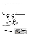
2. Turn the pump off, disconnect the cell and tri-sensor cords,
and remove the manifold piping (without the cell) to a clean
working area. See diagram for which unions to remove (marked ➀in diagram above).
3. Locate the label on the manifold assembly marked “Optional Tap Points” (marked ② in diagram above), and drill the
appropriate mounting hole adjacent to where indicated on the label marked “Acid In”. Do not drill through the label!
Use a drill stop attachment if available, or wrap a piece of masking tape, exposing 1” of the tip of the drill bit as a stop
indicator. This will prevent drilling through the far side of the PVC, damaging the manifold.
Note: Use care to drill the hole perpendicular and deburr, for a leak-free connection of the injector fitting.
Do not over drill or ream the hole as oversized holes will leak and are not covered under warranty.
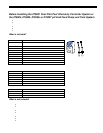
Follow steps #4 and 5 if using AutoPilot factory components or skip to #6 if using Stenner factory components
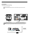
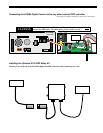
4. Insert the black injector fitting (Uniseal) into the ½” hole.
Note: Do not use any lubrication or sealing compounds!
5. Insert the one-direction check valve assembly into the Uniseal, and then insert the AutoPilot supplied
black plastic tubing (marked 1/8” ID x ¼” OD) onto the check valve. Ensure the tubing is square
edged before inserting (use the utility knife to cut if needed).
Note: If it seems too tight, use some water or dishwashing detergent. Do not use any other lubricants!
6. IF USING THE STENNER FACTORY COMPONENTS, FOLLOW THE INSTRUCTIONS IN THE
STENNER INSTALLAT I O N MAN UAL AN D USE ALL STENNER SUPPLIED T UBI NG
AND FITTINGS as AutoPilot and Stenner factory tubing and fittings are not
interchangeable.
7. If the acid collection tube has not already been installed, do so at this time.
This will connect to the closer fitting on the Stenner head assembly.
8. Roll out the tubing to connect in to the Acid Feed Pump, again ensuring a squared edge.
Leave enough slack in the tubing to secure the tubing with ty-wraps.
! Warning
Avoid any sharp bends and over tightening the Ty-Wrap to the
tubing, which can hinder proper flow of the chemicals
9. Remove the tank access lid and adjust the Stenner acid tank
tubing weight so that it is about 1/2” (1.5 cm) from the bottom
of the tank.
10. Add 1 – 2 gallons of water into the acid tank.
STOP! At this point, turn on the circulation pump and perform the
“Prime Acid Pump”, see pg. 35, and check for any leaks in the acid
tubing and fitting s.
11. Once secured and adjusted, continue adding water and muriatic acid
into the tank for a recommended acid mixture of 4 parts water to 1 part
muriatic acid dilution.
! Warning
To avoid damaging splashes, ALWAYS ADD
ACID TO WATER, never water to acid.
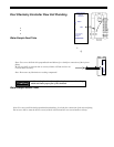
Optional Tap
Points
For
Digital TC
Total Control
Acid In
Water
Out
Tap Poi nt
Locations
Always Ins ert tubing
into appropriate
inlet/outlet.
See Digital TC
manual