


INSTALLATION
20
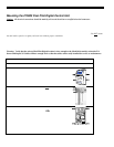
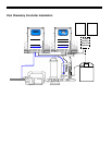
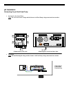
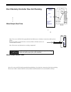
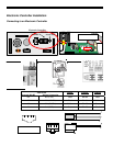
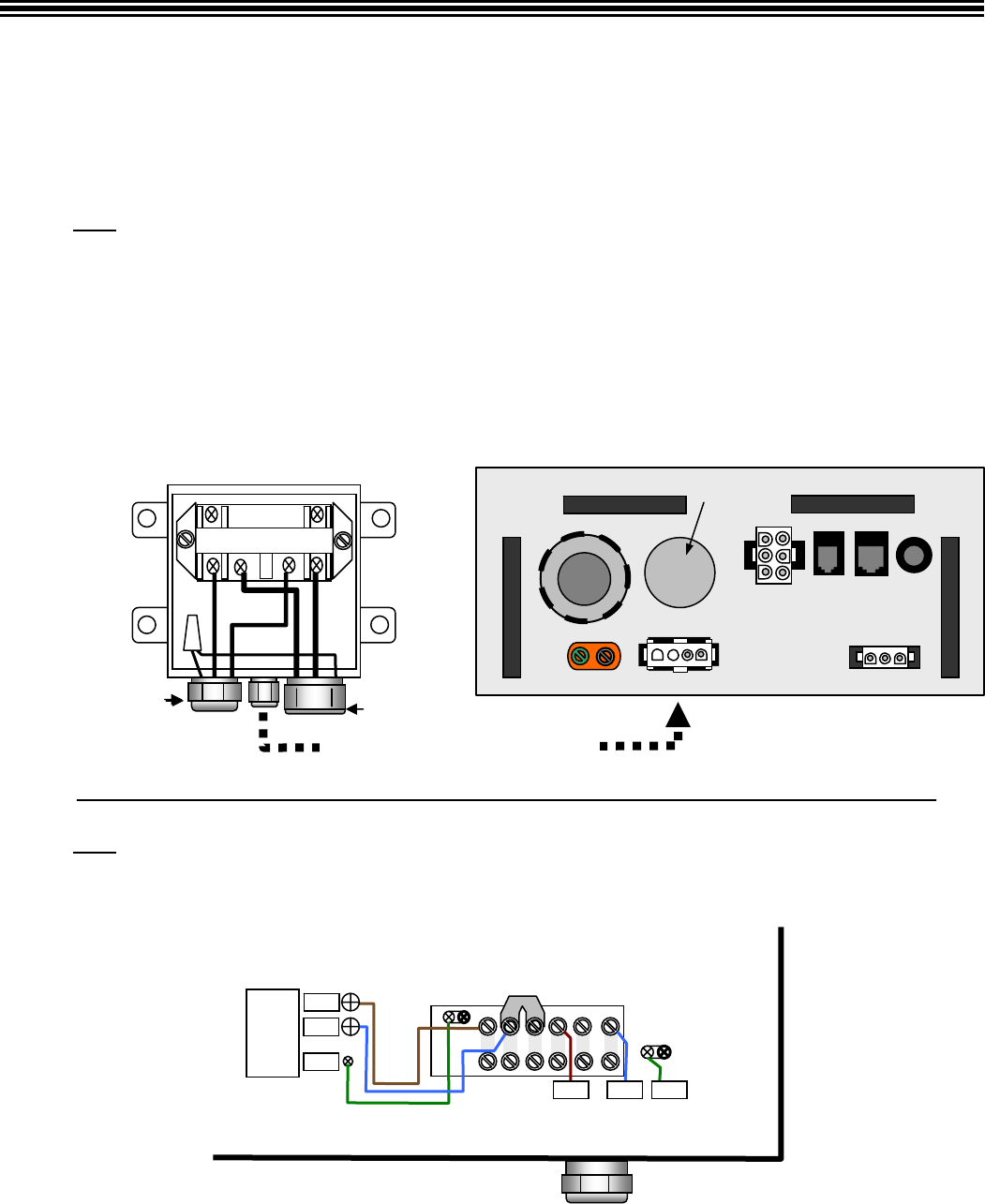
#75003 Digital Control Panel Base Plate
pH Installation
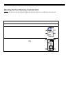
Connecting the pH Acid Feed Pump (Turn off power before making any electrical connections)
The electrical instructions will depend on the Set Relay 1 configuration of the Pool Pilot Digital (#75003) – see pg. 34.
• One Speed or Two Speed Pump – Digital is controlling the main circulation pump
Note:
The AC Power Source voltage and the Stenner Acid Feed Pump voltage must match one another.
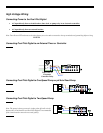
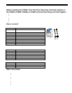
(Auxiliary Relay Kit, #75008 is required - complete mounting and wiring instructions are included with the kit):
1. Mount the #75008 Auxiliary Relay box the proper distances between the Control Unit and acid feed pump and tank.
2. Plug the flat 4-position conn ector into the Digital unit base plate, shown below as #75008 Auxiliary Relay Terminal.
3. Route the Input ac power wires through Liquidtite conduit, from the AC Power Source to the Auxiliary Relay. These
wires should be connected to the Auxiliary Relay terminals marked Line 1 an d Line 2.
4. Cut off the existing ac plug on the acid feed pump and route this cord into the Auxiliary Relay, through the strain
relief fitting provided on the Relay box, shown below as “To Acid Pump”.
5. Cut back the cord jacket approximately 3” (7.2 cm) and strip the wires approximately ½” (1.5 cm).
6. Insert these wires into the Auxiliary Relay terminals marked Load 1 and Load 2.
7. Connect the Green Ground wires together with the provided wire nut, and then go to Step 4 below.
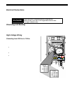
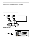
• Acid Pump – Digital is controlling the Stenner Acid Pump
Note:
The Pool Pilot Digital voltage and the Stenner Acid Feed Pump voltage must match one another.
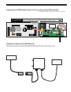
1. Cut off the existing ac plug on the acid feed pump and route this cord into the Pool Pilot Digital Control unit Control
Unit, through a strain relief fitting provided with the pH Acid Feed Pump Installation Kit.
2. Cut back the cord jacket approximately 3” (7.3 cm) and strip the wires approximately ½” (1.3 cm) and insert into
terminal strip #4 and #6.
3. Connect the Green Ground wire to the ground lug.
4. Complete the plumbing of the acid tank – see pg. 22.
5. Set the “Select System” mode to “pH Control” – see pg. 35.
(LINE-OUT) to
Acid Feeder
#1
#2
#3
#4 #5
#6
GND
L1/L
L2/N
To
Circuit
Breaker
GNDL2/NL1/L
#75003 Digital
Control Unit
Terminal Strip
Ground Lug #75008 Auxiliary Relay Terminal
AC Power Conduit or Strain relief fitting for Acid Pump control
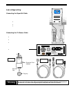
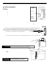
#75008 Auxiliary Relay Kit
Load Line Load Line
1 1 2 2
To Acid Pump
Flexible conduit to ac Power Sour ce
Prewired Plug to #75008 Terminal