


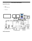
INSTALLATION
9
Before Installing the # 75003 Pool Pilot Digital System
• Determine that everything needed for installation is on hand
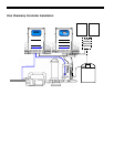
• Determine where the Manifold Assembly will be plumbed
• Find a suitable mounting location for the Control Unit within proper cord length to the manifold
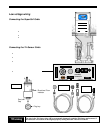
• Plan cord runs for SuperCell Cable and Tri-Sensor Cable
• For optional TC or pH control systems, plan for flow cell water feed tubes and acid feed tube and electrical connections
• Plan wire runs and wiring connections for source power and optional connections if any;
o Determine where input power for the Pool Pilot will orig inate
directly from a circuit breaker
from an external Timer or
from an electronic controller
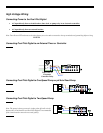
o Determine whether the input voltage for the Pool Pilot is 230Vac (factory configured) or 115Vac
o Determine whether the Pool Pilo t will be used to control a single speed pump or a dual speed pump
o Determine whether the Pool Pilot will be controlled by an ORP controller (or TCC Option)
o Determine whether the Pool Pilot will be controlled by an Electronic Controller system.
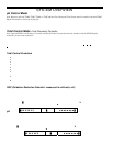
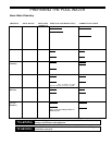
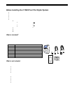
What is included?
Although the manifold assembly may be sold separately, both a manifold and a Pool Pilot Digital Control unit are required for a
complete installation and start-up. The standard cell/manifold assembly is available with the following cells: SC-36, SC-48, SC-
60 (residential cells), or the CC-15 (commercial cell). Before attempting the installation, check that the following items have
been included with th e Pool Pilot Pool Pilot Digital Control unit:
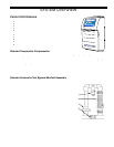
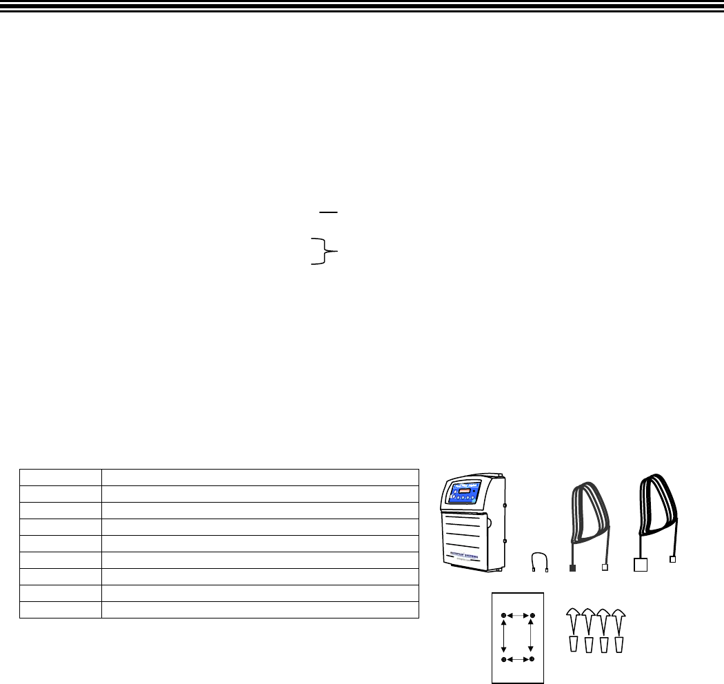
DIGITAL CONTROLLER
Quantity Item Description
1 # 75003 Pool Pilot Digital Control Unit
AC jumper for 11 5 Vac configuration
1 Tri-Sensor Cable
1 SuperCell Cable
1 Mounting Template
4 Plastic Anchors
4 Mounting Screws
*2 68mm x 2” metric adapters (#19059)
* European Systems only
What is not included
Some of the additional equipment that may be needed to complete the installation:
For any installation
• Appr o pri at e ga uge electrical wire
• ½”liquidtite (non-metallic flex) conduit
• ½” conduit connector for service to the Pool Pilot
• Drill
• ¼” masonry drill bit
For installations using optional equipment
• Appr o pri at e ga uge electrical wire
• ½” liquidtite (non-metallic flex) conduit
• ½” conduit connector for filter pump
• Cable for connection for ORP interface (PN # 315-AC)
• 4-Conductor cable for connection to Electronic Controller option
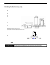
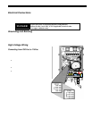
Pool Pilot is to be wired to the same location as the main filter pump
so that it only activated when the pump is energized.
Digital Time clock is used to control the main pump
or pump is also running off the breaker
CHECK
SYSTE
M
BOOST MENU SELECT PUMP
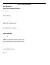
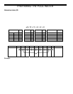
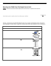
MOUNTING
TEMPLATE
Drill (4) ¼
cations.
Drill o
Sean Assam