


INSTALLATION
21
➀
②
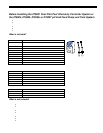
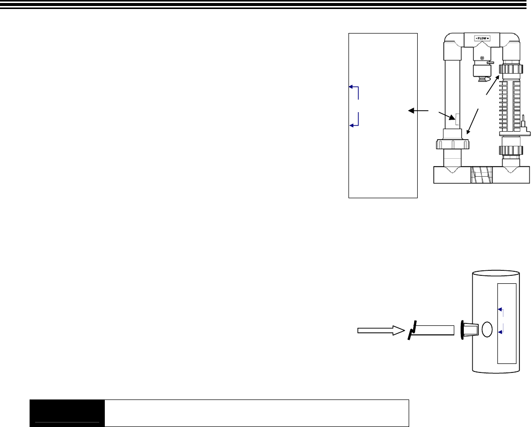
Optional Tap Points
For
Digital TC
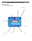
Total Control
A
cid In
Water Out
Tap Point
Locations
A
lways Insert tubing
into appropriate
inlet/outlet.
See Digital TC manual
for drilling instructions.
Optional Tap
Points
For
Digital TC
Total Control
Always Insert
tubing
into appropriate
inlet/outlet.
See Digital TC
manual
for drilling
instructions.
Acid In
Water
Out
Tap Poi nt
Locations
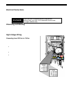
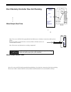
Pool Chemistry Controller Flow Cell Plumbing
It is necessary to have a constant flow to the flow cell to ensure accurate water
sampling. This is done by locating the water sample tubes as indicated in the
diagram on pg. 16.
Have these tools on hand prior to starting this step:
• Drill
• 1/2” standard drill bit
• Utility knife
Water Sample Feed Tube
A hole must be drilled into the manifold assembly for installation of the injector
fitting for the Water Sample Feed Line.
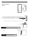
1. Turn the pump off, disconnect the cell and tri-sensor cords, and remove the manifold piping (without the cell) to a
clean working area. See diagram above for which unions to remove (m arked ➀ in diagram).
2. Locate the label on the manifold assembly marked “Optional Tap Points” (marked ② in diagram), and drill the
appropriate mounting hole adjacent to where indicated on the label marked “Water Out”. Do not drill through the
label! Use a drill stop attachment if available, or wrap a piece of masking tape, exposing 1” of the tip
of the drill bit as a stop indicator. This will prevent drilling through the far side of the PVC, damaging
the manifold.
Note: Use care to drill the hole perpendicular and deburr, for a leak-free connection of the injector
fitting.
Do not over drill or ream the hole as oversized holes will leak and are not
covered under warranty.
3. Insert the Uniseal fitting into the hole.
Note: Do not use any lubrication or sealing compounds!
4. Insert the Black Water sample tube approx 1” into the Uniseal fitting.
5. Roll out the tubing and connect into the Flow Cell Inlet valve (left side), ensuring a squared edge.
6. Leave enough slack in the tubing to secure the tubing with ty-wraps.
!Caution
Avoid any sharp bends and over tightening the ty-wrap to the tubing,
which can hinder proper flow of the chemicals
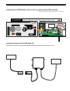
Water Sample Return Tube
The Flow cell sample return tube must be connected to the suction side of the circulation pump. This can be done by drilling a ½”
hole in the pipe and using the Uniseal fitting, or by Drill and Tapping, then threading the Stenner ¼” NPT fitting in the pipe.
Using the Uniseal fitting (Turn Pump Off prior to drilling into the pip e):
1. Mark a spot on a straight section of suction pipe into the pump. Make sure it is after all suction valves and directly into
the pump suction.
2. Drill a ½” hole. Use a drill stop attachment if available, or wrap a piece of masking tape, exposing 1” of the tip of the
drill bit as a stop indicator. This will preven t drilling through the far side of the PVC, damaging the pipe.
Note: Use care to drill the hole perpendicular and deburr, for a leak-free connection of the injector fitting.
Do not over drill or ream the hole as oversized holes will leak and are not covered under warranty.
3. Insert the Uniseal Fitting into the hole.
4. Insert the black water sample tubing into the suction side fitting.
5. Roll out the tubing and conn ect into the Flow Cell Outlet valve (right side), ensuring a squared edge.
6. Leave enough slack in the tubing to secure the tubing with ty-wraps.
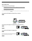
7. Install the ORP and pH sensors as shown on pg. 19.
8. Turn the pump on and check for leaks.
A 6” section of tubing can be inserted into the water sample valve (middle valve) to allow better access to take a water
sample from the flow cell.