


INSTALLATION
12
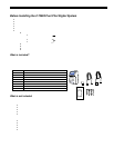
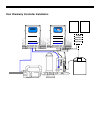
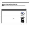
Mounting the #75003 Pool Pilot Digital Control Unit
Caution: All electrical connections should be made by a licensed electrician or certified electrical contractor.
Your Pool Pilot Digital is suitable for indoor or outdoor moun ting. If it is connected to 230 Vac, it must be installed at least 5’
(1.5m) horizontal distance from the pool or spa wall (or more if local codes require). If it is connected to 115 Vac, it must be
installed at least 10’ (3m) horizontal distance from the pool or spa wall.
The Pool Pilot Digital is designed to mount vertically on a flat surface with the wiring inputs facing downward. The enclosure is
designed to allow heat to dissipate from inside the box. It is important not to block the top or bottom of the box. Do NOT
mount
the unit inside a panel or a tightly enclosed area without proper ventilation.
The cover of the Pool Pilot Digital is removed from the sides by four thumbscrews so it is advisable to leave adequate space on
the sides for hand access to the thumbscrews.
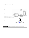
When selecting a location for installing the Pool Pilot Digital, please note that the Tri-Sensor and SuperCell cables are 12’ (3.6 m)
long.
Warning: Verify that the selected Pool Pilot Digital location is close enough to the Manifold Assembly so that the Tri-
Sensor and SuperCell Cables will have enough slack so that the cables can be easily handled for service or maintenance.
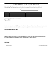
Read the following section completely before proceeding (damage to wires and connectors may occur):
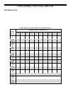
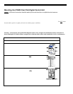
1. Level and tape the mounting template to the selected mounting location. Mark the wall for the 4
mounting h ol es.
2. Plastic anchors and screws have been provided for concrete or stucco walls. Drill and install the plastic
anchors and/or screws. Leave a ¼” gap from the wall when tightening the screws.
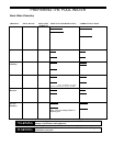
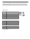
3. Loosen but do not remove the 4 thumbscrews on the sides of the Control Unit.
(2 thumbscrews on each side)
4. Carefully slide off the outer housing cover. Disconnect the 3 plugs that
connect to the display board (indicated by ) that is mounted inside
the cover. (The display circuit board does not need to be removed from
the cover.)
5. Safely set the cover aside.
6. Hang the Pool Pilot Digital on the four mounting screws.
Using a long shaft slotted screwdriver, tighten the screws through
the black plastic access holes (indicated by ).
7. For access to the electrical terminal strip, remove the four screws
and lift off the inner metal protective cover.
8. Route the (2) ribbon connectors from the display circuit board side through
the slotted access hole, then remove the (1) power plug on the po wer circ ui t
board side and route through the slotted access hole.
9. Safely set the metal protective cover aside.
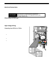
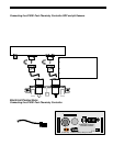
10. See Electrical Connections on pgs. 13 – 15 fo r te rminal connections.
11. Reverse steps 3 - 8 to re-install the metal and outer covers. Make sure to route and connect the ribbon
connectors and power plug through the metal protective cover properly, then replace the outer housi ng
cover after first connecting the 3 plugs (that were disconnected in Step 4).
CHECK
SYSTEM
BOOST MENU SELECT PUMP