


INSTALLATION
11
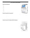
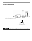
Plumbing the Manifold Assembly
Step 1: Select the location for installing the manifold:
The manifold is designed for a flow rate of 20 to 100 gpm (76 to 379 L/m).
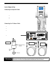
• It is recommended that the manifold be installed prior to installation of the control unit. The Contro l Unit will need
to be installed close enough to the Manifold Assembly so that the Tri-Sensor and SuperCell Cables (12’ long) will
have enough slack so that the cables can be serviced easily.
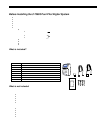
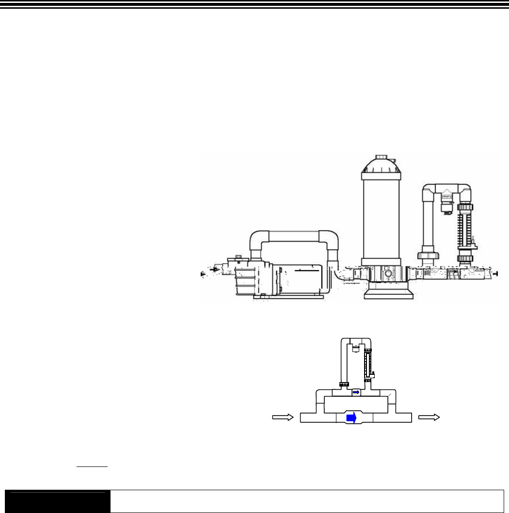
• The manifold/cell should be installed in a vertical orientation as illustrated in the p icture below. Th is orientation
prevents hazardous gas buildup in the system if the flow switch should fail to detect in sufficient flow.
• The direction of the water flow through the manifold must be as indicated for the system to wor k pr operly.
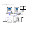
• For a Pool/Spa combination, the
manifold must be located as the
last component in the POOL
RETURN LINE to avoid over-
sanitization of the SPA.
For flow rates within the normal range:
• The manifold can be directly
plumbed into the system as shown
in the diagram to the right.
• If the flow rate for the system is
less than 20 gpm (76 L/m),
a larger pump must be installed.
Note: Ensure that flow rates for a two-
speed pump can provide sufficient flow at low speed.
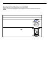
For flow rates greater than 100 gpm (379 L/m):
• A 5 lb spring bypass check valve must be
plumbed in parallel with th e manifo ld as
shown in the diagram to the right.
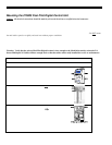
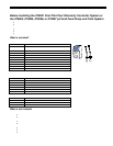
Step 2: Install the cell into the manifold with the cell cable terminals at the bottom of the manifold as illustrated in the picture.
Tighten the unions by hand
for a watertight seal. The manifold will accept the SC-36, SC-48, SC-60 residential cells, or the
CC-15 commercial cell.
! WARNING
If the cell is improperly installed upside down, water from rain or other sources may enter
the cable contacts and result in failure of the SuperCell and void your warranty.
5 lb bypass valve
Main Flow
To Pool Return