


INSTALLATION
10
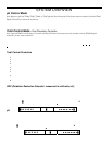
Plumbing Requirements
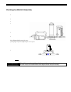
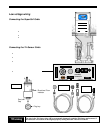
The Manifold Assembly is 2” Schedule 40 and is typically plumbed into the pool return line and, if applicable, after the heater
and spa return diverter valve.
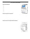
Electrical Requirements
Power must be shut off at the circuit breaker before performing any wiring. All local and NEC electrical codes should be
followed.
The Pool Pilot Digital has been factory configured for 230Vac operation. If it needs to be reconfigured for 115Vac operation,
then see Converting from 230 Vac to 115Vac on pg. 13.
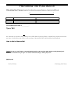
Installation Steps
Details on each step of the installation process are presented on the following pages:
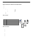
1. Plumbing the Manifol d Asse mbly (pg. 11)
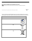
2. Mounting the Pool Pilot Digital (pg. 12)
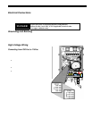
3. Electrical connections (pgs. 1 3 - 15 )
a. Grounding and bo nding
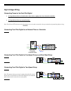
b. High voltage wiring
i. Pool Pilot Digital to an external timer or controller
ii. Pool Pilot Digital relay for a One-speed pump or pH acid feed pump (optional)
iii. Pool Pilot Digital relay for a Two speed pump output (optio nal)
iv. Pool Pilot Digital relay for acid feeder (optional)
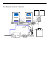
c. Low voltage wiring
i. SuperCell cable
ii. Tri-Sensor cable
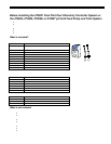
4. #75001 Pool C hemistry Cont rol l e r Co n fi g uration – optio nal (p gs. 16 - 23)
5. Electronic Control Configuration – optional (pg. 24)
6. Menu Overview (pg. 25)
7. System Startup and programming (pgs. 26 - 37)