


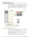
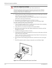
XW System Accessories Installation
5–6 975-0239-01-01
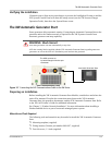
4. Connect the network cable(s) (and terminator if necessary) to either input on the back
of the XW System Control Panel. See Figure 5-4.
Connect a network terminator to the XW System Control Panel if it is the last device
at the end of a series-type network layout.
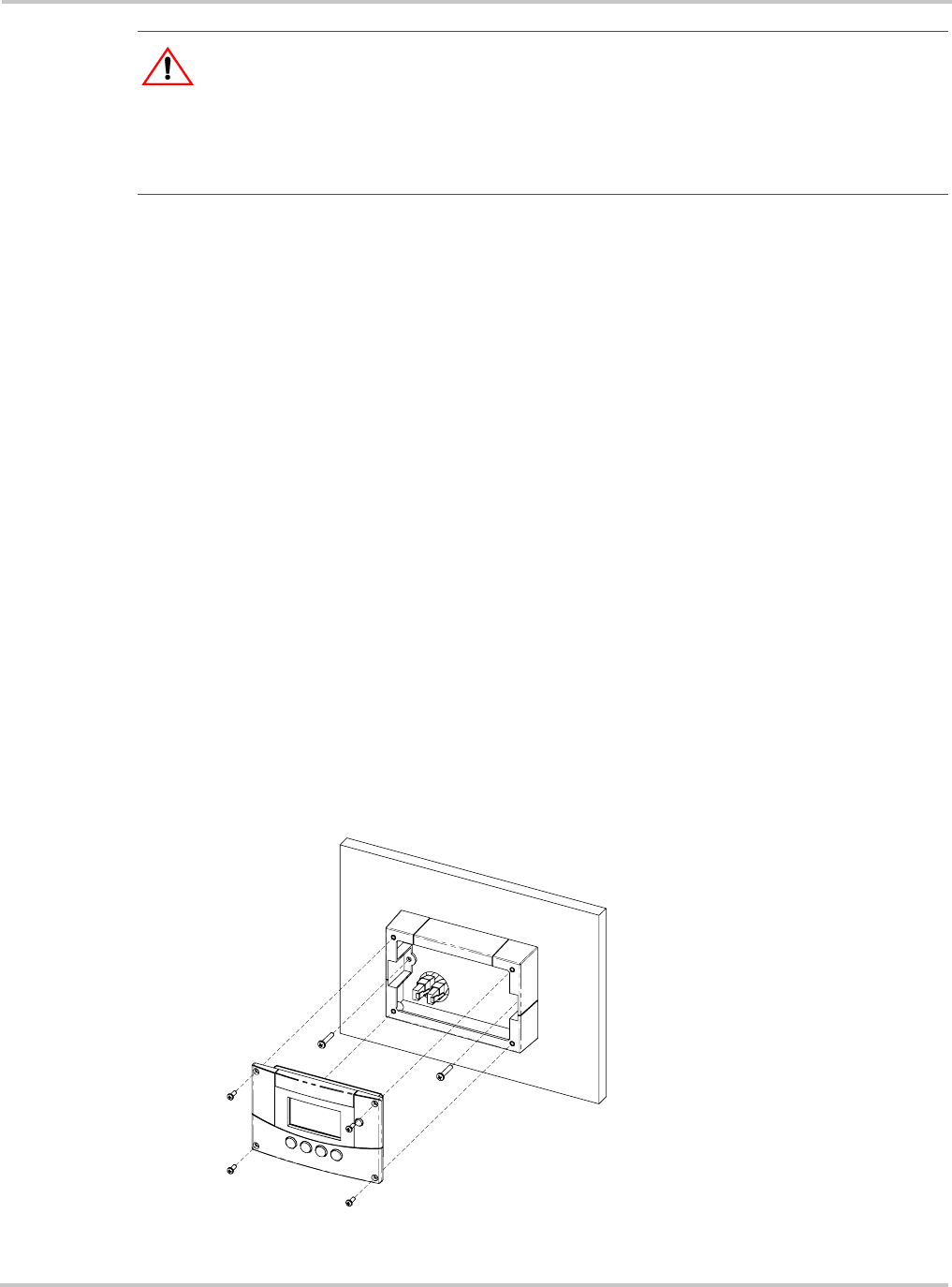
5. Place the unit in the opening and secure it with four #6 screws.
6. Peel off the protective plastic coating covering the screen and indicator light.
To surface mount the XW System Control Panel:
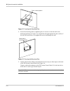
1. Using the supplied template sticker as a guide, mark the locations for two mounting
screws and the access hole for the network cables.
2. Using a hole saw, cut out the access hole for the network cable(s).
3. Route the network cable(s) from other Xanbus-enabled devices inside the wall and
through the access hole.
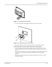
4. Attach the mounting plate with two #6 screws.
5. Connect the network cable(s) (and terminator if necessary) to either input on the back
of the XW System Control Panel.
Connect a network terminator to the XW System Control Panel if it is the last device
at the end of a series-type network layout.
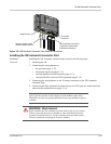
6. Place the unit into the mounting plate and secure it with four #6 screws. See Figure
5-6.
7. Peel off the protective plastic coating covering the screen and indicator light.
:
CAUTION: Equipment damage
Connect the XW System Control Panel only to other Xanbus-enabled devices.
Although the cabling and connectors used in this network system are the same as Ethernet
connectors, this network is not an Ethernet system. Equipment damage may result from
attempting to connect these two different systems.
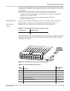
Figure 5-6
Surface Mounting the XW System Control Panel