


Inverter/Charger Installation
2–36 975-0239-01-01
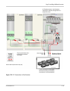
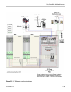
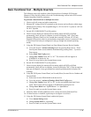
AC Wiring for a Triple-Inverter System
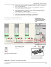
1. Prepare power distribution bars (supplied in 865-1020) by cutting away one of the
four tabs, only three tabs per power distribution bar are required in a three inverter
system. A total of 6 distribution bars should be prepared.
2. Mount the nine breakers on the din rail and install power distribution bars as follows:
a) Two distribution bars, L1 and L2 at the input (top) terminals of the INV1, INV2
and INV3 Grid breakers.
b) Two distribution bars, L1 and L2 at the input (top) terminals of the INV1, INV2
and INV3 Gen breakers.
c) Two distribution bars, L1 and L2 at the output (bottom) terminals of the INV1,
INV2 and INV3 AC Load breakers.
3. Connect L1 and L2, AC wiring from each INV Grid breaker to the corresponding AC
Input (AC1) terminal on each of the three inverters.
4. Connect L1 and L2, AC wiring from each INV Gen breaker to the corresponding AC
Input (AC2) terminal on each of the three inverters.
5. Connect L1 and L2, AC wiring from each INV AC Load terminal from each of the
three inverters, to the corresponding AC INV Out breaker terminal in the PDP.
6. Connect L1 and L2, AC Load wiring to the INV Out (AC Load) power distribution
bar.
7. Connect L1 and L2, AC wiring from the Generator disconnect to the Gen breaker
power distribution bars.
8. Connect L1 and L2, AC wiring from the Utility Grid distribution panel to the Grid
breaker power distribution bars.
9. Connect neutral wiring from INV1 (supplied with PDP), INV2 (supplied in 865-1050)
and INV3 (custom, see material list) to the neutral distribution bar in the PDP.
10. Connect ground wiring from INV1 (supplied with PDP), INV2 (supplied in 865-1050)
and INV3 (supplied in 865-1050) to the ground distribution bar in the PDP.
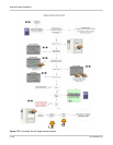
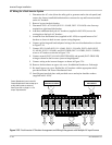
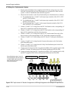
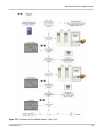
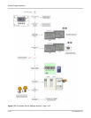
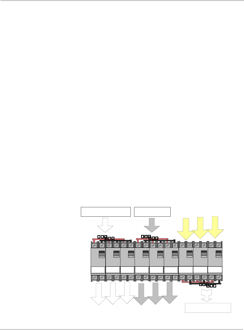
Figure 2-28
Triple-Inverter AC Breaker Arrangement and Wiring Enlargement with Multiple AC Input Sources
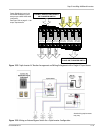
TO AC1 ON INV3
INV 2 IN
(GRID)
INV 1 IN
(GRID)
INV 1 IN
(GEN)
INV 2 IN
(GEN)
TO INVERTER AC DISTRIBUTION
PANEL OR TRANSFER SWITCH
FROM GENERATOR
DISCONNECT
INV 3 IN
(GRID)
INV 3 IN
(GEN)
INV 2 OUT
(AC LOADS)
INV 3 OUT
(AC LOADS)
INV 1 OUT
(AC LOADS)
FROM AC DISTRIBUTION
PANEL OR TRANSFER SWITCH
TO AC1 ON INV2
TO AC1 ON INV1
TO AC2 ON INV3
TO AC2 ON INV2
TO AC2 ON INV1
FROM AC LOAD
ON INV3
FROM AC LOAD
ON INV2
FROM AC LOAD
ON INV1
Power Distribution bars in the XW
Power Distribution Panel accept up
to a #2/0 AWG cable (maximum).
See Figure 2-9 on page 2–11 for
torque requirements.