


Inverter/Charger Installation
2–8 975-0239-01-01
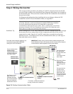
Step 4: Wiring the Inverter
This section provides procedures for making AC and DC connections between the XW
Inverter/Charger and the power distribution panel using the cables that are pre-installed in
the distribution panel. This section also assumes that the XW Conduit Box was installed in
the previous section.
For diagrams and information about installing the inverter/charger without the XW
Conduit Box and XW Power Distribution Panel, see Appendix C.
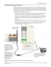
Installation Tip Before making the AC or DC cable connections, route the communications cables through
the raceway, but do not connect them to their components until after all the inverter
connections are made. Once the AC and DC connections are made the run becomes
difficult to access. Use different colors for the communications cables (or cable tags) to
help make them easier to identify.
Important:
Communication and signal cables must be segregated from all DC and
AC wiring. Therefore, a small raceway has been included in the design of both the
XW Power Distribution Panel and the XW Conduit Box to separate the
communications cables from the power cables. This is a small raceway run built into
the bottom of both the XW Power Distribution Panel and the XW Conduit Box and is
held in place by a single screw at the top of the raceway.
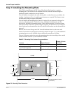
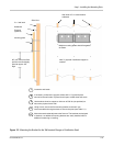
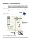
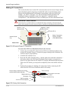
Figure 2-6
Routing Communications Cables
Route the communications cables for any
accessories being installed BEFORE
making AC or DC Connections.
IMPORTANT: When routing communications cables through the XW
Power Distribution Panel, the raceway conduit must be used to keep the
communications cables separate from the power cables.
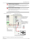
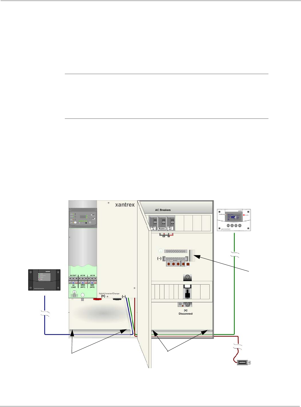
Raceway for Communications
Cables*
Raceway for Communications
Cables*
Do not connect to the
XW Automatic
Generator Start until
all other connections
have been made.
Do not connect to
the XW System
Control Panel until
all other
connections have
been made.
Do not connect to
the BTS to the
batteries until the
battery bank has
been prepared and
is ready to connect
to the inverter.
XW Automatic
Generator Start
XW System
Control Panel
BTS
See Figure 2-12 on
page 2–16 for an
illustration showing
the Communications
Ports and where the
accessories connect.
Raceway for Shunt
Sense cable*.
Raceway exits the
panel through the
back.
*To remove, remove the screws at
the top (Or side) of the raceway.