Installing the Network
975-0239-01-01 3–7
Installing the Network
Before You Begin the Installation
• Read the entire section before installing the network. It’s important to plan the
installation from beginning to end.
• Assemble all the tools and materials required for the installation.
Installation Tools and Materials
Tools The following tools may be required to install the Xanbus cables.
❐ Phillips screwdriver, appropriately sized
❐ Drill and 1/8" bit
Materials The following materials may be required to complete your installation.
❐ CAT 5 or CAT 5e cables (available from Xantrex or computer supply stores)
❐ Network connectors, if installing multi-drop backbone layout
❐ # 6 screws, 2 per each network connector installed
❐ Terminators
Guidelines for Routing the Xanbus Cables
To ensure maximum performance of your network, follow these guidelines when routing
the Xanbus cables.
• Route the cables away from sharp edges that might damage the insulation. Avoid sharp
bends in the cable—no less than a 4-inch (100 mm) radius.
• Allow at least 2 ¼ inches (57 mm) of space behind the wall to accommodate the depth
of the unit and allow room for the cables to bend.
• Allow for some slack in the cable tension.
• Keep the alignment of wire pairs inside the sheath as straight as possible.
• Allow separation between data and power cables (data cables should only cross a
power cable at right angles).
• Do not staple the cable with metal cable staples. Use appropriate hardware fasteners to
avoid damage to the cable.
• Support horizontal cables using J hooks or cable trays.
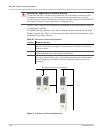
Important:
Do not mix the two types of network layouts. Mixed configurations are not
supported by Xantrex.
Important:
Installing and replacing Xanbus-enabled devices in an existing system must be
performed with the XW Power System in Standby mode. For more information about Standby
mode, see the XW System Control Panel Owner’s Guide.
:
WARNING: Shock hazard
Do not route the Xanbus cables in the same conduit or panel as the AC and DC power cabling.


