


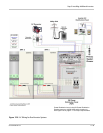
Step 5: Installing Additional Inverters
975-0239-01-01 2–35
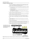
6. Connect positive battery cable for first inverter (supplied with PDP) to top terminal on
first DC disconnect/breaker.
7. Connect positive battery cable for second inverter (supplied in 865-1020) to top
terminal on second DC disconnect/breaker.
8. Connect positive battery cable for third inverter (custom, see material list) to top
terminal on third DC disconnect/breaker.
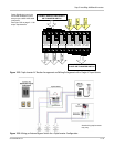
9. Connect positive and negative battery cables to first inverter.
10. Connect positive and negative battery cables to second inverter.
11. Connect positive and negative battery cables to third inverter.
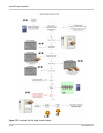
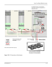
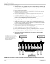
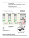
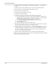
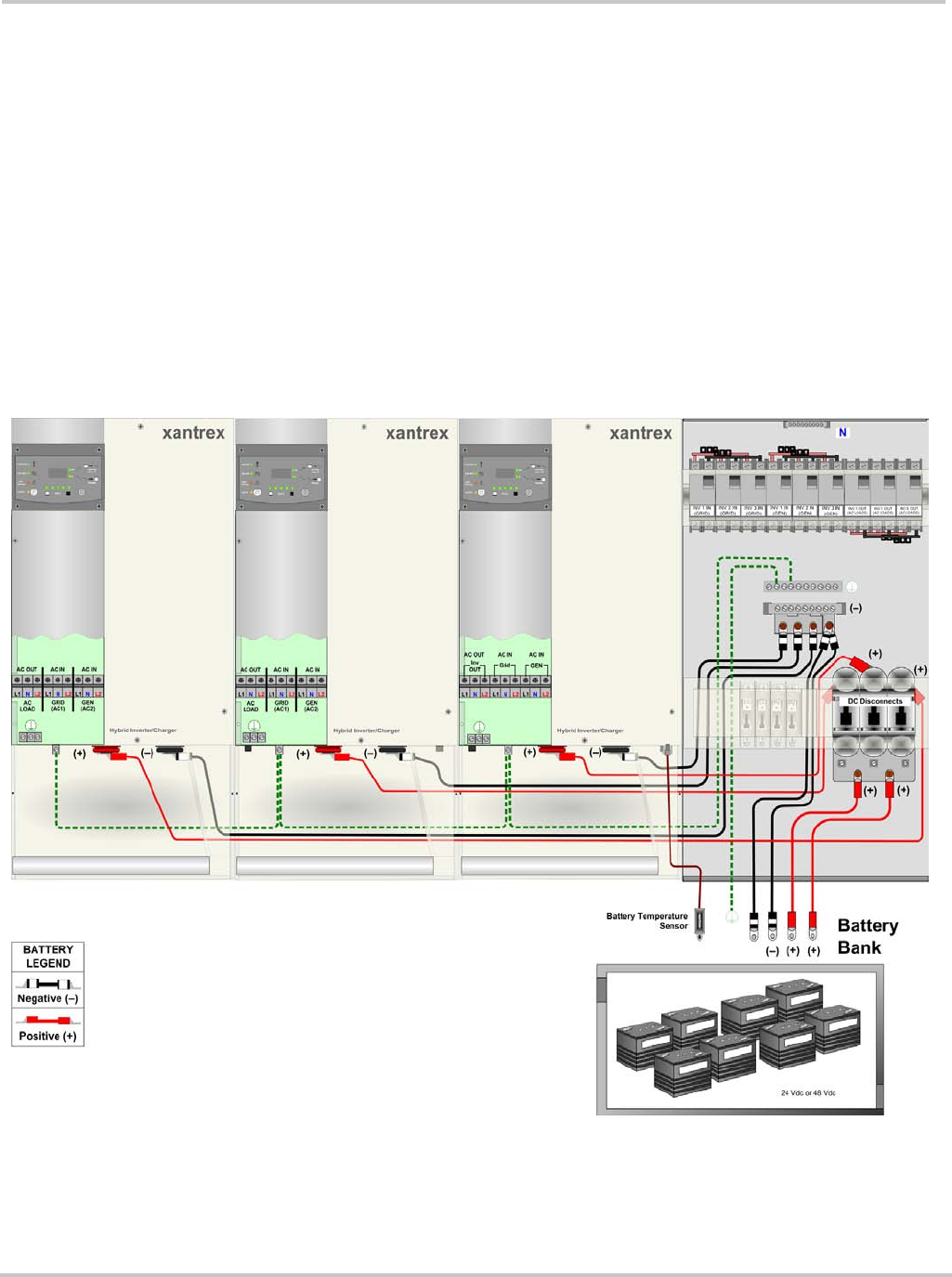
Figure 2-27
DC Connections for a Triple-Inverter System
Actual cable requirements may vary.
Torque connections to the battery
terminals according to the battery
manufacturer’s recommendations.
Torque connections to the
inverter DC terminals to
10-15 ft/lbs.
AC Breakers shown in this
illustration represent the breaker
arrangement for multiple AC
source.
Power Distribution bars in the XW Power Distribution
Panel accept up to a #2/0 AWG cable (maximum).
See Figure 2-9 on page 2–11 for torque requirements.