


Inverter/Charger Installation
2–10 975-0239-01-01
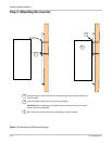
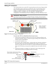
Terminal covers Color-coded snap-on DC terminal covers are provided to prevent accidental contact with
the terminals. Terminal covers are required for all installations, even if a XW Conduit Box
is used. It is also recommended that the shank of the ring terminals (cable lugs) be covered
with heat shrink or some other form of insulation.
Torque Values for the XW Series Inverter/Charger
Table 2-2
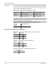
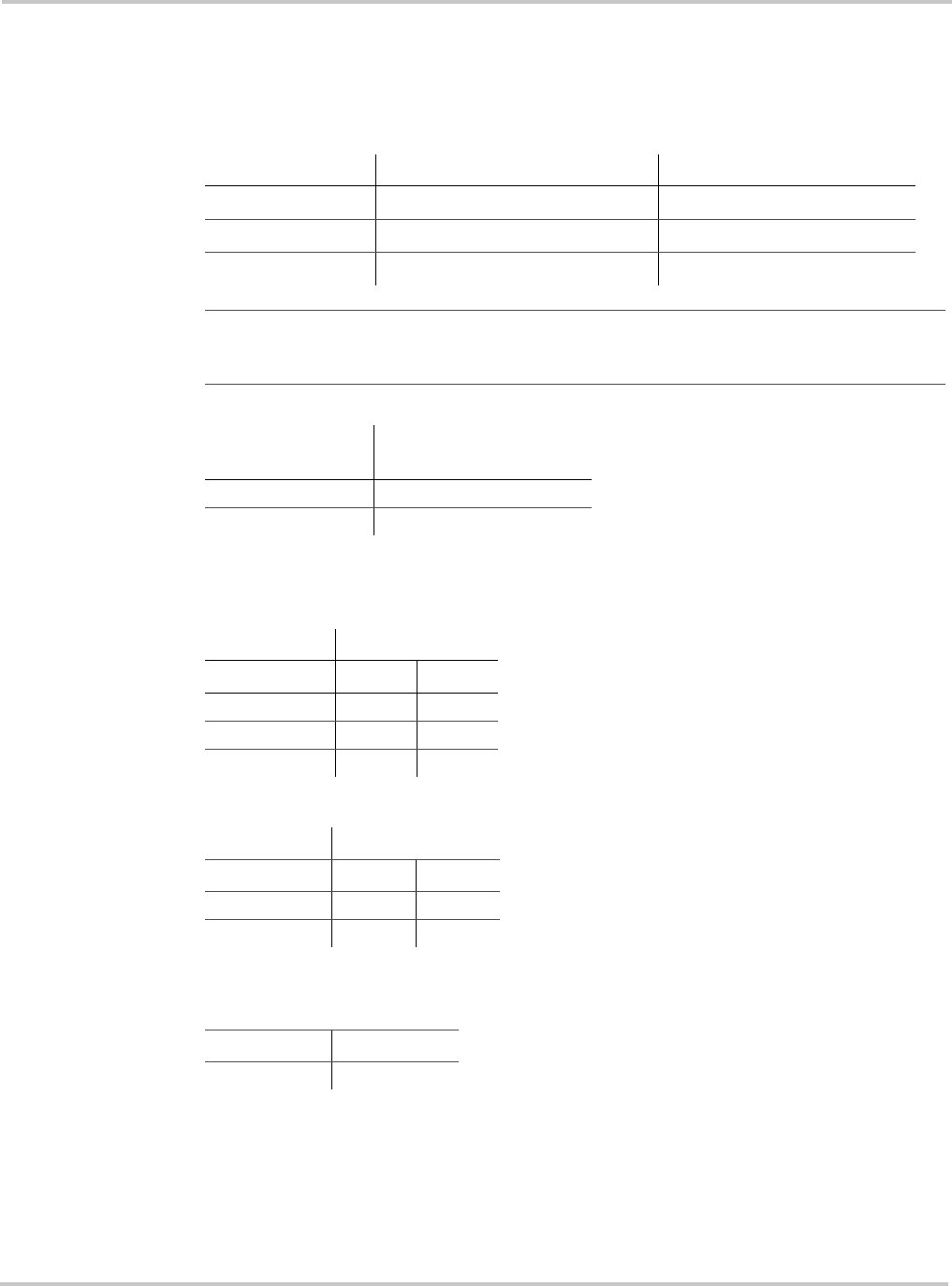
Recommended Battery Cable Size Versus Length
Inverter Model Up to 5 Feet (1.5 m) (90°C wire) Up to 10 Feet (3 m) (90°C wire)
XW4024
#4/0 AWG (120 mm
2
) #4/0 AWG (120 mm
2
)
XW4548
#2/0 AWG (70 mm
2
) #4/0 AWG (120 mm
2
)
XW6048
#4/0 AWG (120 mm
2
) #4/0 AWG (120 mm
2
)
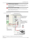
Important:
The NEC/CEC requires both overcurrent protection and a disconnect switch for
residential and commercial electrical systems. These items are not supplied as part of the inverter,
but are included in the XW Power Distribution Panel.
Table 2-3
Battery Cable (in conduit) to Maximum Breaker/Fuse Size
Cable Size
Required
Maximum Breaker/Fuse
Size
#2/0 (00) AWG 175 amps
#4/0 (0000) AWG 250 amps
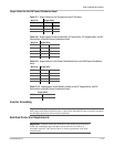
Table 2-4
Torque Values for AC Wiring (AC Terminals and Ground Bar)
Wire Size Torque Value
AWG In-lb N-m
14–10 35 4
8404.5
6–4 45 5
Table 2-5
Torque Values for the Chassis Ground Lug
Wire Size Torque Value
AWG In-lbs N-m
6-4 45 5.1
3-2 50 5.6
Table 2-6
Torque Values for the Inverter Battery Terminals
Torque Value
Ft-lbs N-m
15 20.4