


XW System Accessories Installation
5–14 975-0239-01-01
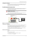
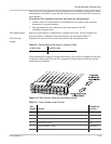
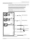
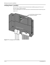
Connecting an External Manual ON/OFF Switch (optional)
The external manual ON/OFF inputs (wires 7 and 8 on the wiring harness) are intended for
wiring to one or more remote ON/OFF switches for starting and stopping the generator
manually. The other contact of the switch should be connected to ground. In order for the
XW Automatic Generator Start to be able to detect these switches, wire the positive of the
generator battery to the constant 12-volt/24-volt generator battery positive (wire 10 on the
XW Automatic Generator Start wiring harness). See Figure 5-7.
If the generator battery does not have the required voltage, any 12-volt or 24-volt power
source will suit this purpose. If an alternate power source is used, the negative of the
power source must be connect to the other contact of the switch.
Multiple control panels or simple contact closures can be wired to the external manual
ON/OFF inputs. The XW Automatic Generator Start detects if any of the contacts close
and will change its operating mode to External Manual On or External Manual Off (for
more information, see the XW Automatic Generator Start Owner’s Guide). The XW
Automatic Generator Start turns the generator on or off according to these inputs and the
resulting operating mode change.
The External Manual On and External Manual Off states are not affected by maximum
generator run time. See the XW Automatic Generator Start Owner’s Guide for additional
information.
CAUTION: Equipment Damage
Do not connect the XW Automatic Generator Start to a 48-volt battery bank. The
XW Automatic Generator Start is limited to a 30V open-circuit maximum by its
regulatory approval and cannot be connected to a 48-volt power source.
Furthermore, tapping 12-volts or 24-volts from a 48-volt battery bank will
unevenly wear out the batteries and shortens the battery bank life.
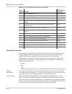
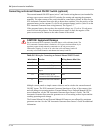
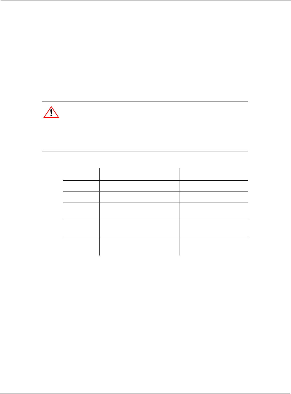
Table 5-6
Wiring for Connecting an External Manual ON/OFF Switch
Wire Number Function Wiring Harness Wire Color
7 External manual on input White/Green
8 External manual off input White/Red
9 External On/Off LED Indicator
output
White/Blue
10 Constant 12/24 V B+ for
External On/Off/LED Indicator
Red
11 External On/Off/LED Indicator
return
Black