


Inverter/Charger Installation
2–20 975-0239-01-01
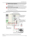
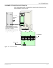
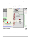
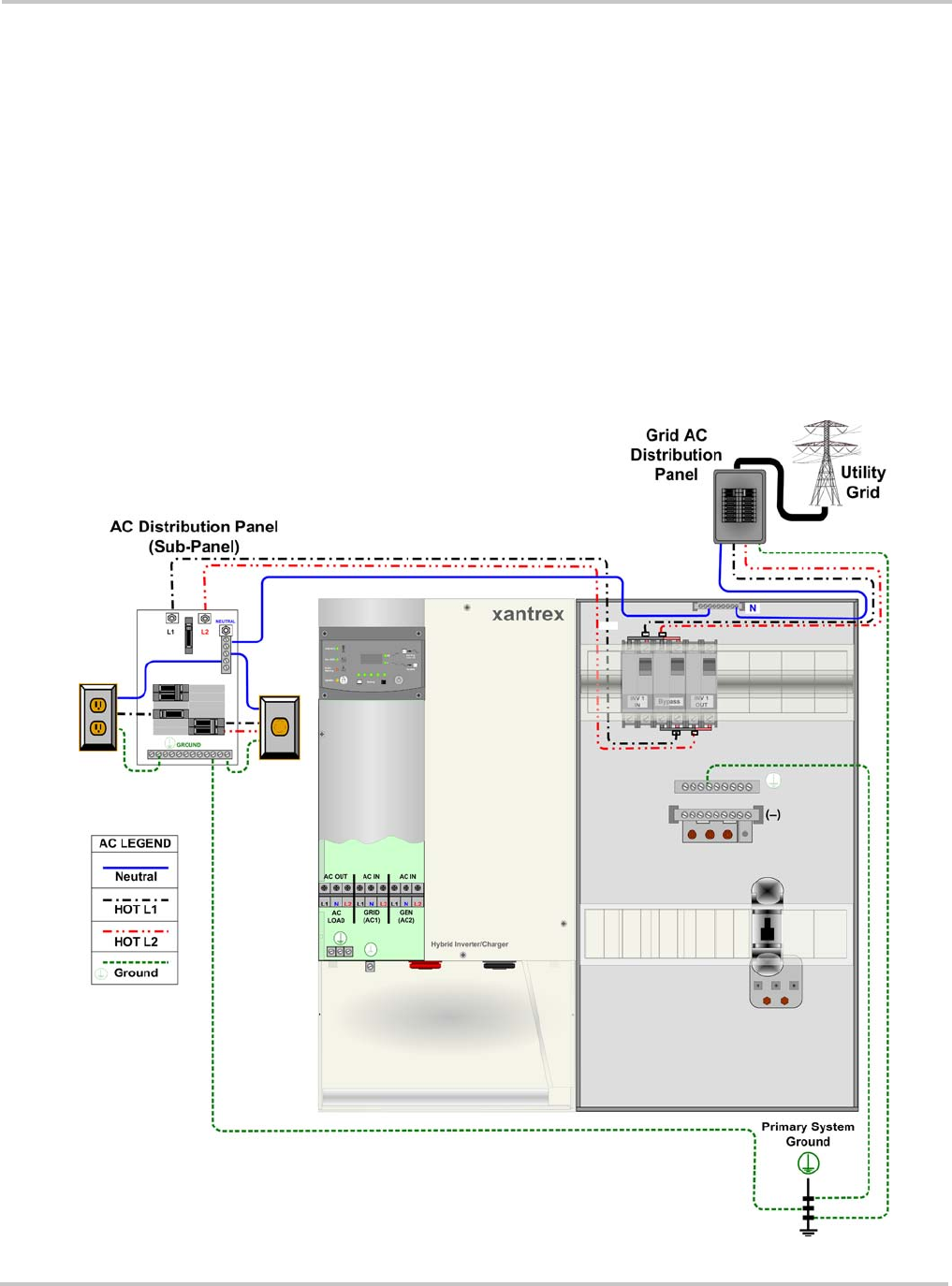
2. Connect the wires labelled “INV1 L1-GRID” and “INV1 L2-GRID” to the inverter. If
the AC source will be the utility grid, connect to the GRID (AC1) terminals
(L1-GRID, L2-GRID). If the system will be off-grid and the only AC source will be a
generator, these wires can be connected to the GEN (AC2) terminals (L1-GEN,
L2-GEN). No additional neutral connection is needed when using the XW Power
Distribution Panel. (Additional neutral terminals (N-GRID, N-GEN) are provided on
the inverter for installations that do not use the XW Power Distribution Panel.)
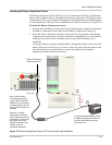
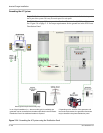
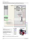
3. Connect L1 (from the L1 output Power Distribution Bar) and L2 (from the L2 output
Power Distribution Bar), Neutral, and Ground to the sub-panel that supplies power to
inverter loads.
4. Connect L1 and L2 from the input side of the AC1 Breaker (L1 and L2 Power
Distribution bars) to the utility grid AC Panel. Connect Neutral from the XW Power
Distribution Panel to the utility grid AC panel. Connect the ground wire between the
XW Power Distribution Panel and the utility grid AC panel.
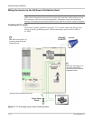
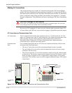
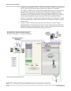
Figure 2-15
Wiring the XW Power Distribution Panel to the Sub-panel or Utility Grid
Actual wiring requirements may vary.
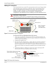
Power Distribution bars in the XW Power Distribution
Panel accept up to a #2/0 AWG cable (maximum).
See Figure 2-9 on page 2–11 for torque requirements.