


975-0239-01-01 xi
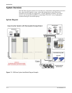
Figure 1-1 XW Power System Installation Diagram Example - - - - - - - - - - - - - - - - - - - - - - - - - - - - -1–2
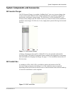
Figure 1-2 XW Inverter/Charger- - - - - - - - - - - - - - - - - - - - - - - - - - - - - - - - - - - - - - - - - - - - - - - - - 1–3
Figure 1-3 XW Conduit Box - - - - - - - - - - - - - - - - - - - - - - - - - - - - - - - - - - - - - - - - - - - - - - - - - - -1–3
Figure 1-4 Power Distribution Panel and XW Conduit Box - - - - - - - - - - - - - - - - - - - - - - - - - - - - - - - 1–4
Figure 1-5 XW Connection Kit for INV2 - - - - - - - - - - - - - - - - - - - - - - - - - - - - - - - - - - - - - - - - - - - 1–5
Figure 1-6 XW Solar Charge Controller- - - - - - - - - - - - - - - - - - - - - - - - - - - - - - - - - - - - - - - - - - - -1–6
Figure 1-7 XW System Control Panel - - - - - - - - - - - - - - - - - - - - - - - - - - - - - - - - - - - - - - - - - - - - -1–6
Figure 1-8 Automatic Generator Start - - - - - - - - - - - - - - - - - - - - - - - - - - - - - - - - - - - - - - - - - - - - -1–7
Figure 2-1 Clearance Requirements- - - - - - - - - - - - - - - - - - - - - - - - - - - - - - - - - - - - - - - - - - - - - - -2–3
Figure 2-2 Mounting Plate Dimensions - - - - - - - - - - - - - - - - - - - - - - - - - - - - - - - - - - - - - - - - - - - -2–4
Figure 2-3 Mounting the Bracket for the XW Inverter/Charger or Distribution Panel- - - - - - - - - - - - - -2–5
Figure 2-4 Mounting the XW Inverter/Charger - - - - - - - - - - - - - - - - - - - - - - - - - - - - - - - - - - - - - - -2–6
Figure 2-5 Installing the XW Conduit Box - - - - - - - - - - - - - - - - - - - - - - - - - - - - - - - - - - - - - - - - - -2–7
Figure 2-6 Routing Communications Cables - - - - - - - - - - - - - - - - - - - - - - - - - - - - - - - - - - - - - - - - -2–8
Figure 2-7 DC Grounding Using a Power Distribution Panel - - - - - - - - - - - - - - - - - - - - - - - - - - - - - 2–12
Figure 2-8 Battery Temperature Sensor (RJ11) Port Location and Installation - - - - - - - - - - - - - - - - - 2–13
Figure 2-9 XW Inverter/Charger DC Connections - - - - - - - - - - - - - - - - - - - - - - - - - - - - - - - - - - - - 2–14
Figure 2-10 Battery Cable Connection- - - - - - - - - - - - - - - - - - - - - - - - - - - - - - - - - - - - - - - - - - - - - 2–14
Figure 2-11 DC Connections to a Single Inverter Using a XW Power Distribution Panel- - - - - - - - - - - 2–15
Figure 2-12 XW Inverter/Charger AC Connections and Communications Ports - - - - - - - - - - - - - - - - - 2–16
Figure 2-13 AC Terminal Block - - - - - - - - - - - - - - - - - - - - - - - - - - - - - - - - - - - - - - - - - - - - - - - - - 2–17
Figure 2-14 Grounding the AC System using the Distribution Panel- - - - - - - - - - - - - - - - - - - - - - - - - 2–18
Figure 2-15 Wiring the XW Power Distribution Panel to the Sub-panel or Utility Grid - - - - - - - - - - - - 2–20
Figure 2-16 Wiring the Inverter to the XW Power Distribution Panel- - - - - - - - - - - - - - - - - - - - - - - - 2–21
Figure 2-17 Generator Wiring Using a XW Power Distribution Panel- - - - - - - - - - - - - - - - - - - - - - - - 2–22
Figure 2-18 AUX Port Location - - - - - - - - - - - - - - - - - - - - - - - - - - - - - - - - - - - - - - - - - - - - - - - - - 2–23
Figure 2-19 Power-up Display - - - - - - - - - - - - - - - - - - - - - - - - - - - - - - - - - - - - - - - - - - - - - - - - - - 2–25
Figure 2-20 Enable the Inverter - - - - - - - - - - - - - - - - - - - - - - - - - - - - - - - - - - - - - - - - - - - - - - - - -2–26
Figure 2-21 Checking AC Voltage - - - - - - - - - - - - - - - - - - - - - - - - - - - - - - - - - - - - - - - - - - - - - - - 2–27
Figure 2-22 Checking Charging Operation - - - - - - - - - - - - - - - - - - - - - - - - - - - - - - - - - - - - - - - - - - 2–27
Figure 2-23 Functional Test for Single Inverter Systems- - - - - - - - - - - - - - - - - - - - - - - - - - - - - - - - - 2–28
Figure 2-24 DC Connections to Dual Inverters - - - - - - - - - - - - - - - - - - - - - - - - - - - - - - - - - - - - - - - 2–31
Figure 2-25 Dual Inverter AC Breaker Arrangement and Wiring Enlargement with
Multiple AC Input Sources - - - - - - - - - - - - - - - - - - - - - - - - - - - - - - - - - - - - - - - - - 2–32
Figure 2-26 AC Wiring for Dual-Inverter Systems- - - - - - - - - - - - - - - - - - - - - - - - - - - - - - - - - - - - - 2–33
Figure 2-27 DC Connections for a Triple-Inverter System - - - - - - - - - - - - - - - - - - - - - - - - - - - - - - - 2–35
Figure 2-28 Triple-Inverter AC Breaker Arrangement and Wiring Enlargement with
Multiple AC Input Sources - - - - - - - - - - - - - - - - - - - - - - - - - - - - - - - - - - - - - - - - - 2–36
Figure 2-29 Triple-Inverter AC Breaker Arrangement and Wiring Enlargement with a
Single AC Input Source - - - - - - - - - - - - - - - - - - - - - - - - - - - - - - - - - - - - - - - - - - - 2–37
Figure 2-30 Wiring an External Bypass Switch for a Triple-Inverter Configuration- - - - - - - - - - - - - - - 2–37
Figure 2-31 Installing the AC Sync Cable - - - - - - - - - - - - - - - - - - - - - - - - - - - - - - - - - - - - - - - - - - 2–38
Figure 2-32 Functional Test for Multiple Inverters - Page 1 of 2 - - - - - - - - - - - - - - - - - - - - - - - - - - - 2–41
Figures