


Xanbus Network Installation
3–4 975-0239-01-01
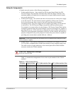
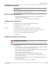
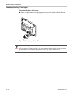
• Network terminators (Figure 3-3)—the Xanbus network must be properly terminated
at each end with male or female network terminators to ensure the communication
signal quality on the network. If the network is not properly terminated, signal quality
is degraded and performance on the network is reduced. Permanent configuration
without terminators is not supported by Xantrex. The XW Series and other
Xanbus-enabled devices ship with one male terminator already installed. Depending
on your network layout, this terminator may need to be removed and inserted into
another device elsewhere in the network.
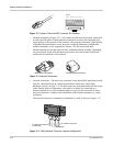
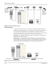
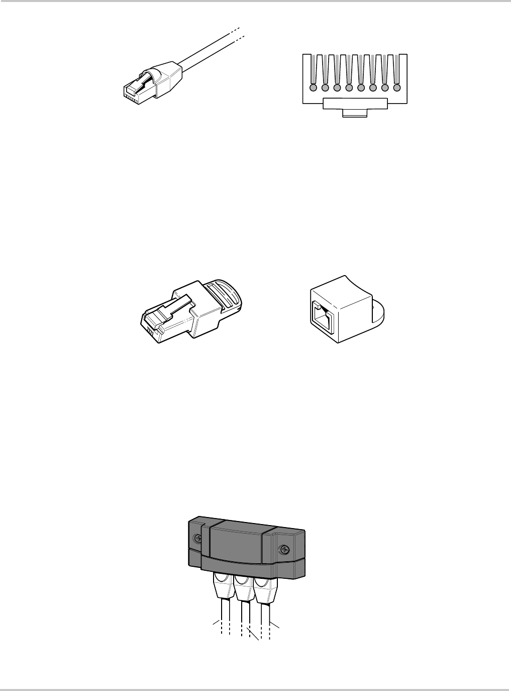
• Network connectors—The three-way connector houses three RJ45 inputs that provide
a device connection point on a multi-drop backbone layout (see “Multi-Drop
Backbone Layout” on page 3–5). All three inputs are wired identically and can accept
either Xanbus cables or terminators. One input is available for connecting to a
Xanbus-enabled device. The remaining inputs are reserved for connection to other
network connectors, a Xanbus cable terminated with a female terminator, or a male
terminator.
The network connector is mounted to a bulkhead or a wall, as shown in Figure 3-4.
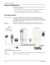
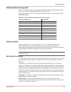
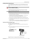
Figure 3-2
Xanbus Cable and RJ45 Connector Pin Numbers
Pins:
8 7 6 5 4 3 2 1
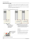
Figure 3-3
Network Terminators
Male network terminator
Female network terminator
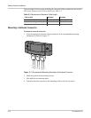
Figure 3-4
3-Way Network Connector (sample configuration)
To network connector
To network connector
or teminator
To device