


Basic Functional Test - Single Inverter
975-0239-01-01 2–25
Basic Functional Test - Single Inverter
The following steps will complete a basic functional test of the XW Inverter/Charger. If
any test fails, please refer to the Troubleshooting section in the XW Inverter/Charger
Operation Guide for assistance.
Confirm All Connections
Once the AC and DC wiring have been installed and connected, take a moment to go back
over all connections and make sure they are secure and have been installed correctly.
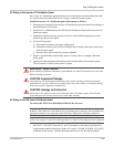
Applying DC Power to the Inverter
To apply DC power to the inverter:
1. Before applying DC power to the inverter, measure the voltage and polarity of the
cables (measure at the battery side of the disconnect or breaker).
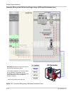
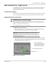
2. Apply battery (DC) power to the inverter by closing the battery bank DC disconnect.
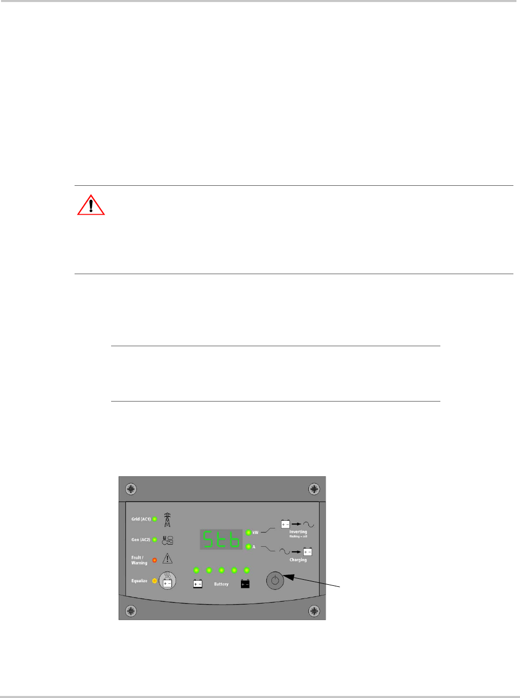
The inverter will power up, the display will illuminate, but the inverter will remain in
the Standby Mode (as shown in Figure 2-19).
CAUTION: Reverse Polarity Damage
Before making the final DC connection or closing the DC breaker or disconnect, check cable
polarity at both the battery and the inverter/charger. Positive (+) must be connected to positive (+).
Negative (–) must be connected to negative (–).
Reverse polarity damage is not covered by warranty.
Important:
Voltage should be between 40 to 60 volts for a 48-volt
system, and 20 to 30 volts for a 24-volt system. If the DC voltage is low,
the battery bank needs to be charged externally. Charge the battery bank
and restart the functional test.
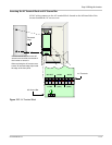
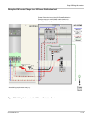
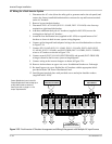
Figure 2-19
Power-up Display
ON/OFF Button
All LEDs temporarily illuminate.
Note: If the inverter was
previously powered up then it will
power-up in the last operating
state (Operating or standby)