


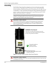
Wiring
975-0239-01-01 4–9
Wiring
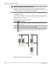
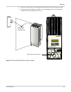
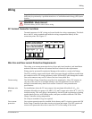
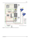
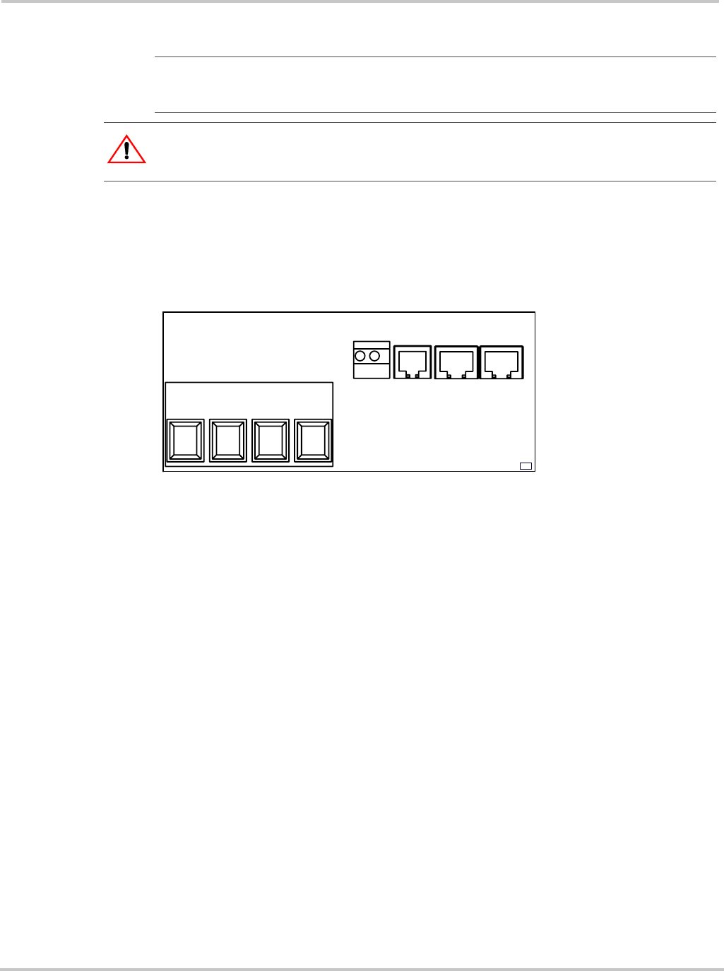
DC Terminal Connector Locations
Terminal connectors for DC wiring are located inside the wiring compartment. The labels
above the DC wiring terminals and inside the wiring compartment identify all the
connection points. See Figure 4-7.
Wire Size and Over-current Protection Requirements
The wiring, over-current protection devices (fuses and circuit breakers), and installation
methods used must conform to all national and local electrical code requirements.
Wiring must be protected from physical damage with conduit or a strain relief clamp.
The BTS, auxiliary output, and network cables must pass through a different conduit than
the conduits used for PV wiring and battery cables. Pull the BTS cable through the conduit
first as the connector may not fit if other wires have been pulled first.
Current rating The XW Solar Charge Controller is rated for 60 A maximum I
sc
. Since PV outputs can
vary due to the array size or sunlight striking it, the safe minimum wire size must be
chosen for maximum array short-circuit current. Consult PV array manufacturer
specifications.
Minimum wire
gauge
For installations where the PV array output is the maximum allowable 60 A I
sc
, the
minimum allowable wire gauge is #6 AWG (13.3 mm
2
) copper wire with a 90 °C (194 °F)
insulation rating. This wire gauge is determined by electrical code requirements regarding
conduit knockout sizes, wire bending radius, and space available within the XW Solar
Charge Controller wiring compartment.
No crimp-on terminals or lugs are required.
Over-current
protection
Over-current protection must be installed for the battery and PV circuits to protect the XW
Solar Charge Controller from short circuits at its input and output. The NEC requires all
circuits to be protected with a device rated for 125% of the rating of the circuit.
Important:
Installations must meet all local electrical codes. Installations of this equipment
should only be performed by a qualified electrician or a Certified Renewable Energy (RE) System
Installer.
WARNING: Shock Hazard
Disconnect battery and PV sources before wiring.
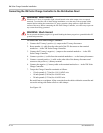
Figure 4-7
DC Connection Terminals
CONNECTIONS DIAGRAM
BTS
AUX
XANBUS
XANBUS
BATTERY
--
-
++
+
BATTERY
TERMINAL TORQUE REQUIREMENTS
15lbf.in (1.7 Nm) FOR #14-10 AWG WIRE
18lbf.in (2.0 Nm) FOR #8 AWG WIRE
20lbf.in (2.2 Nm) FOR #6 AWG WIRE
PV PV