


Inverter/Charger Installation
2–34 975-0239-01-01
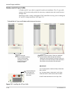
Parts List for a Triple-Inverter Configuration
❐ 1 x XW Power Distribution Panel (PDP) and Accessory kit (mounts to first unit).
❐ 1 x 865-1020 PDP extension kit for second unit.
The following items are required for the third inverter (furthest from PDP) and should be
sourced and prepared prior to the installation. (Note that all wiring will have to be custom
cut to fit the third unit. Wiring supplied with the extension kit is intended for a second
inverter in a two inverter system).
❐ 1 x 865-1020 PDP extension kit.
❐ 2 x AC Distribution Bars (100-0661-01-01).
❐ 2.2 m (87”) x #6 AWG, 600 V, 105°C stranded white wire for neutral
❐ 2.2 m (87”) x #6 AWG, 600 V, 105°C Black stranded wire for L1 Grid (AC1).
❐ 2.2 m (87”) x #6 AWG, 600 V, 105°C Red stranded wire for L2 Grid (AC1).
❐ 2.3m (91”) x #6 AWG, 600 V, 105°C Black stranded wire for L1 Gen (AC2).
❐ 2.3 m (91”) x #6 AWG, 600 V, 105°C Red stranded wire for L2 Gen (AC2).
❐ 2.4 m (95”) x #6 AWG, 600 V, 105°C Black stranded wire for L1 Gen (AC Load).
❐ 2.4 m (95”) x #6 AWG, 600 V, 105°C Red stranded wire for L2 Gen (AC Load).
❐ 1.6m (62”) #4/0 AGW, 105°C, Red stranded with #4/0 x 3/8 lugs crimped at each end
for the positive battery cable.
❐ 1.6m (62”) #4/0 AGW, 105°C, Black stranded with #4/0 x 3/8 lugs crimped at each
end for the negative battery cable.
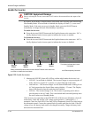
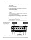
❐ External Bypass Switch - The XW Power Distribution Panel does not have enough
breaker locations to accommodate bypass breakers in a triple-inverter system.
Therefore, an external Bypass Switch may be needed. See Figure 2-30 on page 2–37
for an illustration of how to wire an External Bypass Switch.
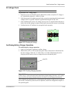
Converting a Single-Inverter Power Distribution Panel to a Triple-Inverter Power
Distribution Panel
◆ Remove upper wire cover and lower wire cover on the XW Power Distribution Panel.
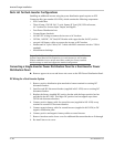
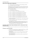
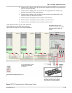
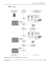
DC Wiring for a Triple-Inverter System
1. Install all three DC disconnect/breakers (two supplied in 865-1020 and one with PDP).
2. Install larger positive distribution plate (supplied in 865-1020).
3. Connect negative battery cable for first inverter (supplied with PDP) to DC negative
distribution plate.
4. Connect negative battery cable for second inverter (supplied in 865-1020) to DC
negative distribution plate.
5. Connect negative battery cable for second inverter (custom, see material list) to DC
negative distribution plate.