


Installing the Network
975-0239-01-01 3–9
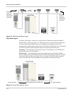
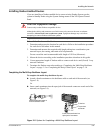
Installing Xanbus-Enabled Devices
If you are installing a Xanbus-enabled device on an existing Xanbus System, put the
system in Standby mode using the System Settings menu on the XW System Control
Panel.
To install the Xanbus-enabled devices:
1. Determine and prepare the location for each device. Refer to the installation procedure
for each device elsewhere in this manual.
2. Determine and measure the required cable length, taking into consideration your
network layout, the routing, and strain relief requirements.
Do not exceed the total recommended cable length of 130 feet (40 meters).
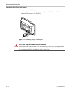
3. Mount the devices according to the installation procedure elsewhere in this guide.
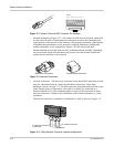
4. Use an appropriate length of Xanbus cable to connect each device and (if used) 3-way
network connector.
5. Terminate the Xanbus network according to “Completing the Multi-Drop Backbone
Layout” on page 3–9 or “Completing the Daisy Chain Layout” on page 3–10.
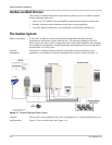
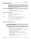
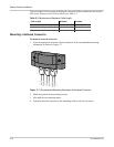
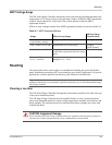
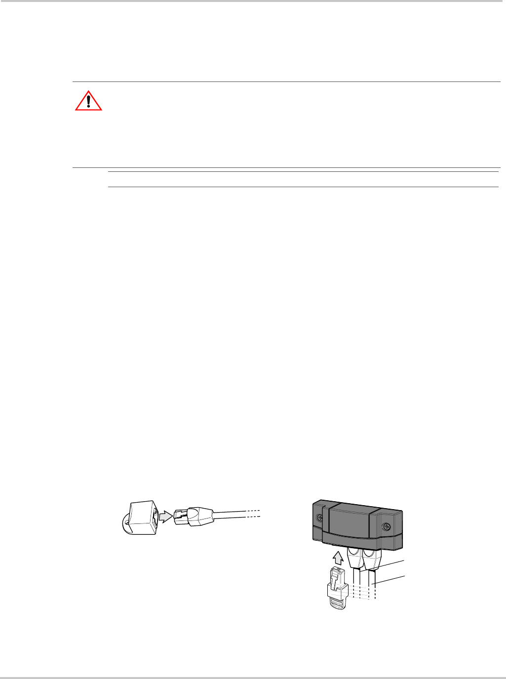
Completing the Multi-Drop Backbone Layout
To complete the multi-drop backbone layout:
◆ Attach a female terminator to the backbone cable at each end of the network (see
Figure 3-8)
Or
◆ Insert a male terminator into the open jack of the network connector at each end of the
network (see Figure 3-8).
CAUTION: Equipment Damage
Connect only to other Xanbus compatible devices.
Although the cabling and connectors used in this network system are the same as ethernet
connectors, this network is not an ethernet system. Equipment damage may result from
attempting to connect Xanbus to different systems.
Important:
Mount cables and network connectors in a dry location.
Figure 3-8
Options for Completing a Multi-Drop Backbone Layout
Attach female terminator to
end of backbone cable.
Insert male terminator into
open jack of connector.
To previous
connector
To device