


Index
IX–2 975-0320-01-01
configuration 2–1
messages in normal operation 5–5
messages in offline mode 5–6
O
operation
factors affecting performance
6–1
inverter startup 4–3
messages at startup 5–2
reassembling the unit 4–2
startup procedure 4–1
P
parallel configuration
communication between inverters
3–12
communications wiring 3–15
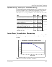
power derating A–4
proof of purchase WA–4
purchase date WA–4
PV arrays
angle of the sun
6–2
checking DC voltage 4–2
effect of shade on performance 6–2
factory ratings 6–1
temperature affecting performance 6–1
types of modules 2–3
voltage requirements 2–3
R
RJ45 ports
communication between inverters
3–13
location in wiring box 3–6
RS-232 port 3–13, 3–15, 5–8
S
safety instructions vii
serial number WA–4
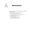
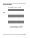
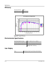
specifications
electrical
A–2
mechanical A–5
standard features and options 1–2
standard test condition 6–1
startup procedure
check PV array DC voltage
4–2
check utility AC voltage 4–2
monitor front panel display 5–1
overview 4–1
replace wiring box cover 4–2
start the inverter 4–3
status LEDs
description
5–11
do not illuminate 6–9
red LED is on 6–9
T
temperature
affecting PV array performance
6–1
range for locating inverter 2–2
terminal blocks in wiring box 3–6
terminators, male network 3–13
thermal derating chart A–3
torque values for wires 3–7
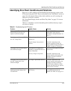
troubleshooting the inverter 6–9
U
utility disconnect settings 5–3, A–3
W
warranty
out of warranty service
WA–3
terms and conditions WA–1
weight A–5
wiring
acceptable wire sizes
A–5
PV array to Xantrex GT Inverter 3–7
torquing 3–7
wire sizes 3–4
wiring box
description
1–3
removing the cover 3–5
removing the inverter from 6–6
RJ45 connectors 3–6
terminal block location 3–6
X
Xanbus technology 3–12
Xantrex web site v