


Replacing Parts
975-0320-01-01 6–7
3. Using an insulated screwdriver, disconnect the PV NEGATIVE (–) wire from
the terminal block inside the inverter. Cap the wire immediately with a wire
nut.
4. Disconnect the remaining AC, DC and network cables between the inverter
and the wiring box, inside the inverter. Cap all disconnected AC and DC wires
with wire nuts.
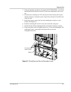
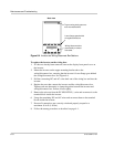
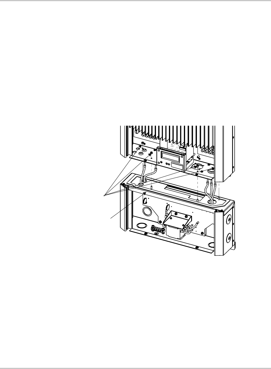
5. Inside the inverter, remove the four nuts attaching the wiring box to the
inverter. See Figure 6-3.
6. Push the connecting DC and AC wires down inside the wiring box.
7. Lift the inverter off the mounting bracket, leaving the wiring box in place.
8. Ensure the gasket on the wiring/disconnect box is clean and undamaged. The
gasket must create a water-tight seal between the inverter and
wiring/disconnect box.
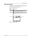
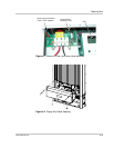
Figure 6-3
Wiring/Disconnect Box and Removable Inverter
Four nuts to
secure inverter
Gasket