


Wiring the Inverter
3–2 975-0320-01-01
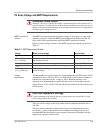
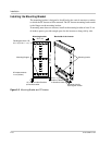
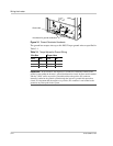
The ground bar accepts wires up to #4 AWG. Torque ground wires as specified in
Table 3-1.
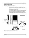
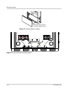
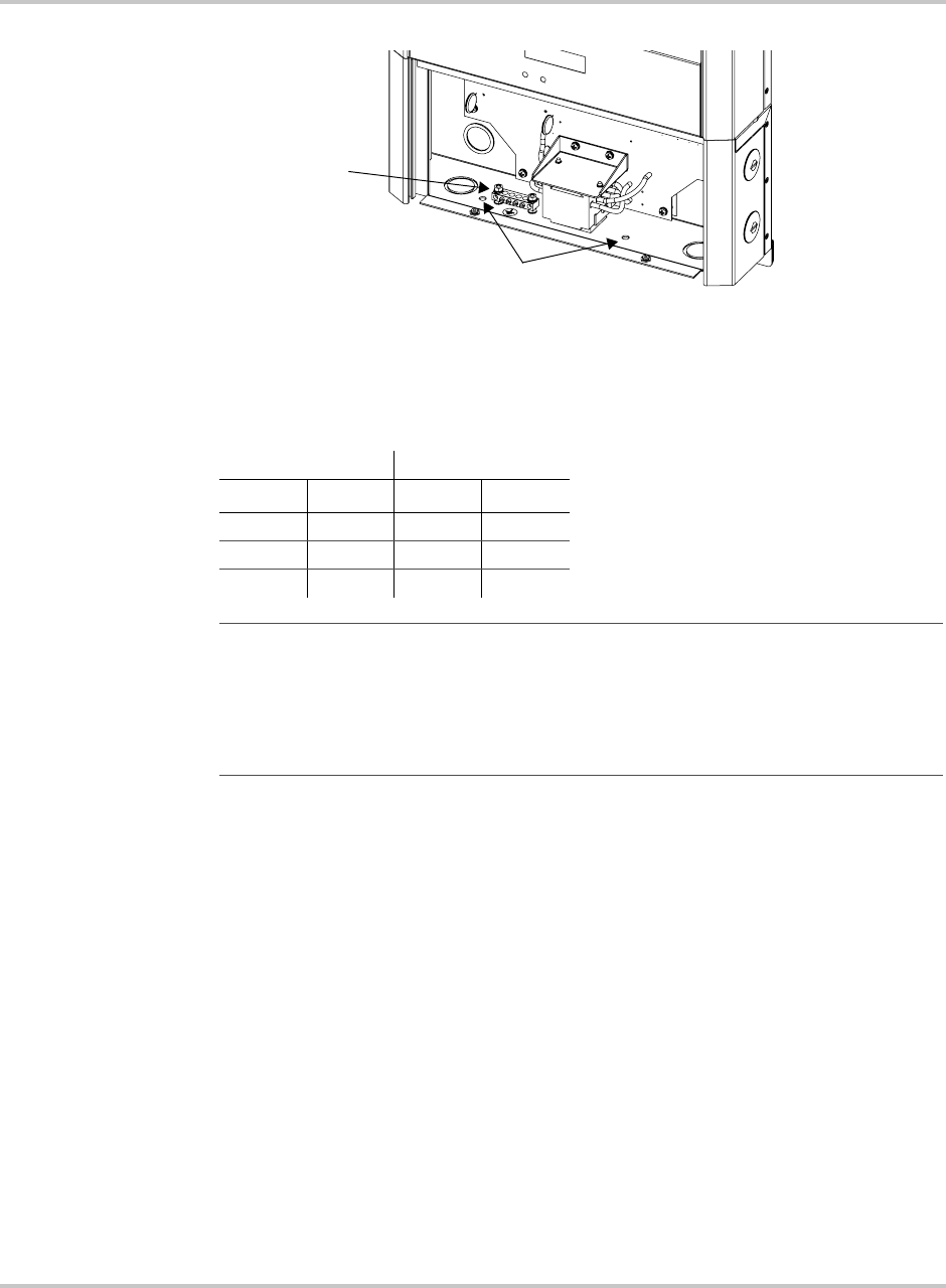
Figure 3-1
Ground Conductor Knockouts
Knockouts for ground conductors
Ground bar
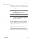
Table 3-1
Torque Values for Ground Wiring
Wire Size Torque Value
AWG mm
2
in-lb Nm
14–10 2.5–6.0 25–35 3.0–4.0
8 10 30–40 3.4–4.5
6–4 16–25 35–45 4.0–5.0
Important:
In most models, the negative PV conductor is internally bonded to the
ground system within the inverter’s ground fault detection circuit. Inverter models marked
with the “-POS” suffix are positive grounded and have the positive PV conductor
internally bonded to the ground system through the inverter’s ground fault protection
circuit. It is important that the negative (or positive) PV conductor is not bonded to the
ground at any other point in the system.