


Wiring the Inverter
3–16 975-0320-01-01
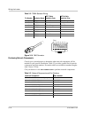
RS-232 cable
requirements
To connect your computer to the GT Inverter, you must use a serial DB9 “straight
through” cable.
The RS-232 connector on the GT is configured as follows:
• Pin 2: transmit
• Pin 3: received
• Pin 5: ground.
All other pins are unused.
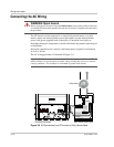
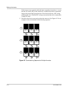
To connect a single GT Inverter to a personal computer:
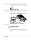
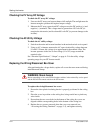
1. Feed the male end of the serial cable through a side conduit hole on the GT
Inverter.
If the end of the serial cable is too large to fit through the conduit hole, you
may need to use two DB9 to CAT 5 adaptors. Plug the DB9 end of the adapter
into the GT Inverter, and feed the CAT 5 end of the cable out the conduit hole.
Use another adapter to convert the CAT 5 end of the cable back to DB9.
2. Plug the male end of the serial cable into the GT Inverter RS-232 port.
3. Plug the female end of the serial cable into your computer’s serial port.
4. Replace the wiring/disconnect box cover.
5. Turn the DC/AC disconnect switch to the ON position and turn the main
utility panel breaker switches ON.
When power is restored to the GT Inverter, you can run GT-View on your
computer to monitor the inverter’s operation.
For more information about GT-View, see the GT-View User Manual, included
with the GT-View software.
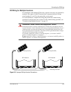
WARNING: Shock hazard
Before opening the GT Inverter wiring/disconnect box, turn OFF the breaker switches
connected to the GT Inverter AC output, and turn the DC/AC Disconnect switch to the
OFF position. Hazardous voltage will still be present on the DC input (PV) terminals
located under the clear plastic insulation barrier. Do not remove the insulation barrier
during this procedure. To reduce the risk of shock, cover the array with an opaque (dark)
material.
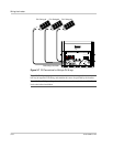
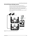
Note: In multiple installations, GT-View monitors only the inverter to which the
computer is connected. However, if the inverters are connected with a Xanbus network
cable, GT-View will display total system wattage and the accumulated daily energy
produced by all inverters. To monitor multiple inverters, you require multiple DB9 cable
connections (one per inverter) to your computer.