


Introduction
1–2 975-0320-01-01
PV compatibility The GT Inverter is designed to take advantage of solar modules configured as high
voltage PV string arrays—single crystalline, poly crystalline, or thin film—with a
240 to 550 Vdc input voltage Maximum Power Point range.
Maximum Power
Point Tracking
(MPPT)
The GT Inverter uses Xantrex proprietary Maximum Power Point Tracking
(MPPT) technology to harvest the maximum amount of energy from the solar
array. Xantrex MPPT learns your array’s specific characteristics, maximizing its
output at all times.
High efficiency The high-frequency, solid-state design of the GT Inverter is extremely efficient—
up to 96.2%.
Expandable Multiple GT Inverters may be networked together for increased net metering
capacity or future system growth. The GT Inverter GT5.0 has adjustable voltage
and frequency disconnect settings and can be aggregated above 30 kW on a single
point-of-common-coupling (PCC). See “Adjustable Voltage, Frequency and
Reconnection Settings” on page A–3.
Communications
protocol
The GT Inverter uses the Xanbus
®
communications protocol, enabling it to
communicate with multiple units connected within the system. For more
information, see “Xanbus Network Technology” on page 3–12.
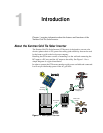
Standard Features
The GT Inverter has the following standard features:
• Sealed inverter section protecting power electronic components;
• Liquid Crystal Display (LCD) providing easy-to-read system status and daily
cumulative energy production information;
• Two LED indicator lights providing status and ground fault indication;
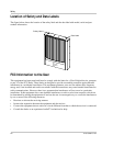
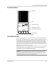
• Wiring/disconnect box providing protection for all AC and DC connections
and eliminating exposed “live” wiring if the inverter is removed.
The wiring/disconnect box has been designed to be physically mated to the
electronics section of the GT Inverter at the factory, but remains in place as a
non-serviceable item in the event that the inverter electronics section is ever
required to be removed. The inverter and wiring/disconnect box together form
an NEMA 3R enclosure to allow outdoor installation.
WARNING: Shock hazard
The 600 volt DC/AC disconnect in the wiring/disconnect box meets NEC Article 690. It is
a non-serviceable component and shall remain in place. Separating the inverter and
wiring/disconnect box, or removing the wiring/disconnect box cover can expose
energized conductors. PV input circuits in the wiring box ahead of the switch remain
energized even when the switch is in the “off” position—hazardous voltage will still be
present on the DC input (PV) terminals under the clear plastic insulation barrier inside the
wiring/disconnect box.