


Accessing the Wiring Terminals
975-0320-01-01 3–5
Accessing the Wiring Terminals
You must remove the GT Inverter wiring box cover to access the terminal blocks,
ground bar and communications ports.
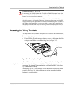
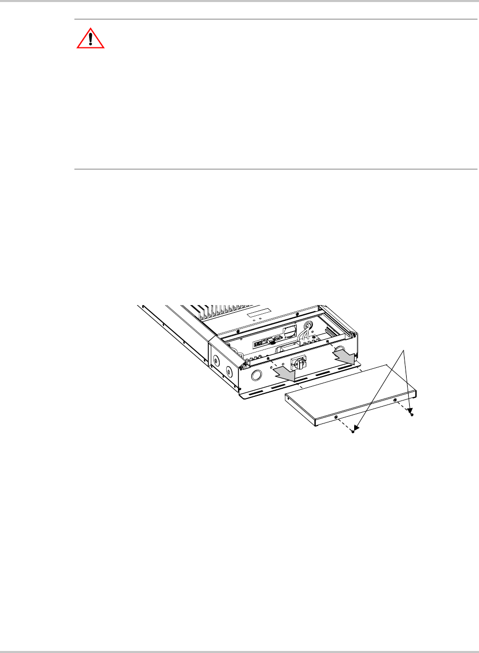
To remove the wiring box cover:
• Using a Phillips screwdriver, remove the two screws on the bottom side of the
wiring box and lift the cover off the wiring box (see Figure 3-3).
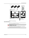
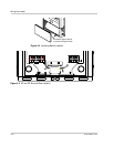
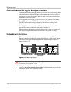
AC and DC connections are made at the wiring terminals shown in Figure 3-5.
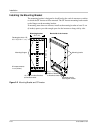
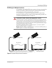
Insulating barrier The clear plastic insulating barrier inside the wiring box is a permanent
component. It is intended to separate the high-voltage AC and DC wiring from
any communications cabling.
When wiring the unit, it is necessary to pull the barrier back to access the wiring
terminals. See Figure 3-4. After completing the wiring, return the insulating
barrier to its original position.
WARNING: Shock hazard
Do not remove the wiring/disconnect box. The 600 volt DC/AC disconnect in the wiring
box meets NEC Article 690. It is a non-serviceable component and shall remain in place.
Removal can expose energized conductors.
Use caution when working around sources of DC power. Although the DC/AC disconnect
switch disconnects the inverter from DC power, hazardous voltages from paralleled PV
strings will still be present upstream of the switch and inside the wiring box. To reduce the
risk of shock during installation, cover the array with an opaque (dark) material before
making any connections, and always test for voltage before touching exposed wiring or
devices.
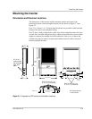
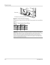
Figure 3-3
Removing the Wiring Box Cover
Wiring box
cover screws