


Installation
2–2 975-0320-01-01
Inverter failure due to improper installation will void the inverter warranty.
Consider the following when determining where to install the inverter.
Indoor/
Outdoor
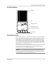
• The GT Inverter uses a Type 3R-rated enclosure (vertical mount only)
that can be mounted indoors or outdoors. (Type 3R enclosures are
intended for outdoor use primarily to provide a degree of protection
against falling rain; and to be undamaged by the formation of ice on the
enclosure.)
• While the 3R-rated enclosure protects the GT Inverter from moisture,
outdoor installations should be located away from lawn sprinklers and
other sources of spray.
• A sun shade is recommended for outdoor installations. In bright sun
conditions, when the GT Inverter is at or near full output with an
ambient temperature above 40 °C (104 °F), shading the unit will help
increase inverter performance. A sun shade can also protect the inverter
from dust, debris, and birds. The sun shade should be made from an
opaque material that provides shade for the heat sink. It should be large
enough and positioned so that it shades the heat sink for all sun angles.
Ensure that the shade is installed according to the minimum clearances
specified on page 2–7.
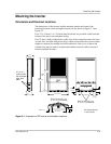
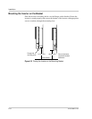
Orientation
• The GT Inverter must be mounted vertically on a wall or pole.
• Do not mount the GT Inverter horizontally.
• If mounting the inverter indoors on a south-facing wall, ensure the wall
is insulated to reduce the amount of heat absorbed by the inverter.
Unless walls are properly insulated, avoid mounting the inverter
indoors on any wall that is directly exposed to the sun.
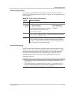
Temperature
• Ensure that the GT Inverter is mounted in a location where the ambient
temperature range is -25 to +65 °C (-13 to +149 °F).
• Above 40 °C (104 °F), the GT Inverter may derate power output.
See“Output Power vs. Ambient Temperature” on page A–3 and
“Environmental Specifications” on page A–4.
• At extreme hot or cold temperatures, the front panel LCD may not
function normally.
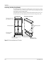
Ground
Clearance
• Outdoors, the GT Inverter requires at least 100 cm (39 inches) of
clearance between the bottom of the unit and the ground.
Distance
• To minimize resistance and resulting power loss, ensure that wire
lengths between the PV array and the GT Inverter and between the
inverter and the Main Utility Service Panel are kept to a minimum.
• Maximum distances will depend on wire gauges used and PV array
output voltages.
Debris free
• Excessive debris (such as dust, leaves, and cobwebs) can accumulate
on the unit, interfering with wiring connections and ventilation. Do not
install in a location where debris can accumulate (under a tree, for
example).