


Mounting the Inverter
975-0320-01-01 2–7
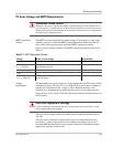
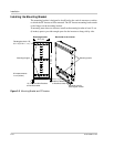
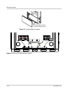
Clearance Requirements
For optimal and safe operation, ensure there is adequate clearance around the
inverter. If the minimum clearances in Table 2-2 are are not met, rated power may
not be achieved.
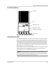
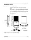
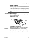
Surfaces for Mounting
The GT Inverter can be mounted to a vertical surface such as wallboard, wood
siding, concrete wall, or pole assembly. Ensure the mounting surface or structure
can support the weight of the inverter (26 kg/58 lb) as well as the associated
wiring and conduit. Installation onto wallboard requires either the use of a
supporting material such as plywood or securing the mounting screws to
supporting wall studs.
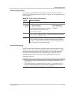
Table 2-2
Inverter Clearance Requirements
Location Minimum Clearance
Above 30 cm (12 inches)
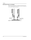
Below:
•Inverter
• Bracket
Outdoors:
• 100 cm (39 inches)
• 110 cm (43 inches)
For indoor installations, there is no clearance
requirement between the bottom of the
inverter and the ground.
The inverter extends
below the bracket by
approximately 10 cm
(4 inches)
In front 30 cm (12 inches) minimum. 91 cm (36 inches) are recommended for
easy access for reading the display, avoiding accidental contact with hot
surface, and servicing the inverter.
On sides
Units can be mounted side by side with no clearance between them, but
15 cm (6 inches) of clearance around the outside edges of the outermost
two units is recommended. In hot climates, some clearance between units
may be needed to prevent thermal derating.
Important:
• Local codes may impose additional mounting requirements in earthquake or other
high-risk areas.
• No mounting hardware is supplied with the GT Inverter. It is recommended to use
6 mm (¼ inch) diameter fasteners. However, because mounting surfaces can vary,
installers must select appropriate hardware for each installation.