


Wiring the Inverter
3–4 975-0320-01-01
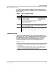
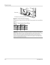
Wiring Requirements
The AC and DC terminal blocks in the GT Inverter accept wire sizes from
#14 AWG to #6 AWG. Undersized wiring can result in significant power losses
and reduction in system efficiency. Strip all wires 9 mm (3/8 inch) and torque to a
maximum 16 in-lb (1.8 Nm). Use copper conductors only, rated 90 °C.
For safety and compliance with the NEC, run AC, DC, and communication wires
in separate conduits.
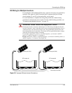
AC Circuit Breaker Requirements
The main utility service panel must dedicate a double pole breaker to operate each
GT Inverter installed. This breaker must be sized to handle the rated maximum
output voltage and current of the GT Inverter (see “Electrical Specifications”,
“Output” on page A–2).
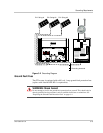
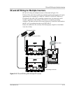
DC/AC Disconnect Switch
The wiring box includes a 600 volt PV/Utility disconnect switch that switches
both AC and DC at the same time.
Depending on the installation, an external AC and/or DC disconnect may be
required if the inverter is installed in a location not easily accessible to utility or
fire personnel. Consult local authorities for additional information.
WARNING: Shock hazard
Check for existing electrical or plumbing prior to drilling holes in the walls.
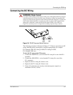
WARNING: Fire hazard
Wiring should not be undersized. Wire sizes must be coordinated with the array maximum
short circuit current or the AC breaker sizes used. Ensure wiring is in accordance with the
NEC or applicable codes.
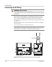
Important:
The DC terminal block has six inputs for connecting up to three PV strings.
In accordance with applicable codes, if the array consists of more than two strings,
external fusing may be required to prevent conductor overloads.