


Disconnect Test
975-0320-01-01 4–5
Disconnect Test
The disconnect test is designed to verify correct operation of the GT Inverter both
on initial operation and periodically through its life as required by the utilities.
This test ensures that the Xantrex Grid Tie Solar Inverter does not send electricity
to the utility grid when the local utility has shut off the grid for repairs, or when
the utility wiring is damaged.
When operation of the inverter has been verified and the unit is producing power,
run the disconnect test as described in this procedure.
To run the disconnect test:
1. Switch off the AC circuit for the inverter. This can be accomplished by
switching the breaker on the main panel that feeds the inverter(s). The
disconnect for the home or business may be used as well.
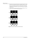
2. Have someone watch the front panel of the inverter to ensure the green light
on the front of the inverter goes out within two seconds.
The green light goes out when the AC circuit is switched off, disconnecting
the inverter from the AC grid. The front panel display will show an AC Fault
display, indicating that the AC is out of the operating range.
3. Switch on the AC circuit for the inverter.
The inverter responds by starting its 305 second protection timer. Ensure that
the inverter does not produce power before the countdown is over. After
completing the countdown, the green light turns on and the inverter begins
delivering power. The display returns to showing the power being produced
and the total kWh produced to date.
4. If you have another GT Inverter to commission, switch off the AC circuit for
the inverter you have just commissioned and tested by switching off the
breaker on the main panel. You can then run the commissioning procedure
and disconnect test on the next inverter.
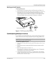
Locating the Firmware Version Number
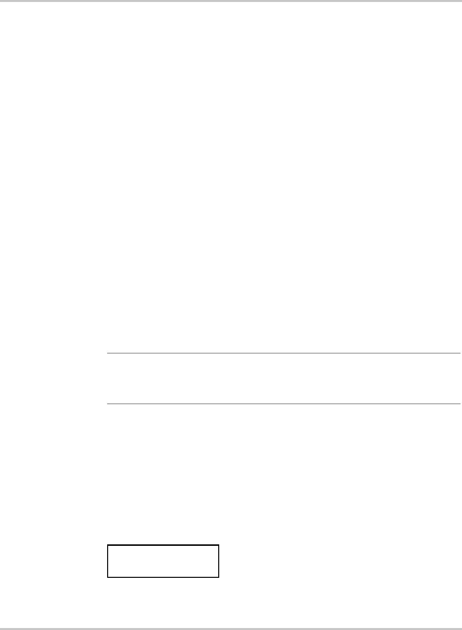
The firmware version number for the protection processor is visible on a screen
that appears when the unit starts up or is powered up after switching the DC/AC
disconnect switch to “on.” The screen reads:
The number appearing after “ROM” is the firmware version number for the
protection processor.
Important:
The default voltage, frequency and reconnect delay values are programmed
into the unit at the time of shipment from the factory. With the utility’s approval, these
settings can be adjusted in the field using the GTConfigLite software tool. See
“Adjustable Voltage, Frequency and Reconnection Settings” on page A–3.
Flash = 03.00
ROM = 03.00