


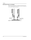
Mounting the Inverter
975-0320-01-01 2–5
Mounting the Inverter
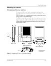
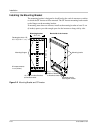
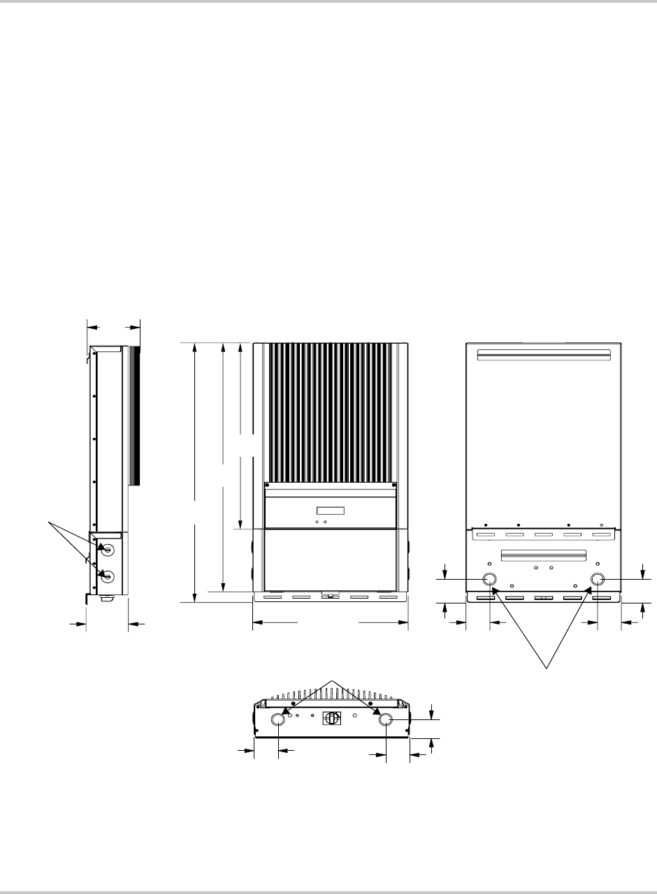
Dimensions and Knockout Locations
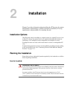
The dimensions of the inverter and the mounting bracket and some of the
knockout locations on the wiring/disconnect box are shown in Figure 2-1 and
Figure 2-2.
Four 27 or 35 mm (1 or 1-3/8 inch) dual knockouts are provided on the back and
bottom of the unit to accommodate wiring.
Four 27 mm (1 inch) conduit holes on the sides of the wiring/disconnect box (two
on each side) are filled with plastic plugs, which can be removed to insert conduit
nipples as required for multiple inverter installations. One or two of these side
conduit holes may be used to accommodate Xanbus network cables connected
between multiple inverters.
Figure 2-1
Dimensions of GT Inverter and Knockout Locations
2.7 cm (1")
conduit holes
with threaded
caps, both
sides
Dual 3.5 cm or 2.7 cm
(1
3/8" or 1") knockouts
13.7
(5
3/8)
11
(4
5/16)
40.3 (15 7/8)
55
(21
5/8)
69.9
(27
1/2)
72.6
(28
9/16)
5.2 (2)
6.2 (2
7/16)
27.9 (11)
All measurements
in cm (inches).
Dual 3.5 cm or 2.7 cm
(1 3/8" or 1") knockouts
6.15
(2
7/16)
6.52
(2
9/16)
27.9 (11)