


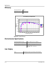

Maintenance and Troubleshooting
6–8 975-0320-01-01
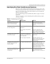
To replace the inverter on the wiring box:
1. If it has not already been removed, remove the display front panel cover on
the inverter.
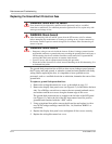
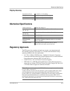
2. Mount the inverter on the upper mounting bracket above the
wiring/disconnect box, ensuring that the inverter’s lower flange goes behind
the wiring/disconnect box. See Figure 6-4.
3. Pull the connecting DC and AC wires back out of the wiring box and into the
inverter.
4. Replace the nuts that connect the inverter and the wiring/disconnect box.
Tighten each nut alternately to clamp the gasket between the inverter and
wiring/disconnect box. Secure all nuts tightly.
5. Remove the wire nut from the PV NEGATIVE (–) wire and reconnect it to the
terminal block inside the inverter.
6. Uncap the remaining DC and AC wires and reconnect them to the terminal
blocks inside the inverter.
7. Ensure all connections are correctly wired and properly torqued to a
maximum 16 in-lb (1.8 Nm).
8. Follow the startup procedure as described on page 4–1.
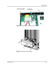
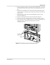
Figure 6-4
Inverter and Wiring/Disconnect Box Sections
Wiring/ disconnect box
permanently mounted
to bracket
Lower flange goes behind
wiring/disconnect box
Back view
Top mounting hook goes over
wall-mounted bracket