


3
Wiring the Inverter
Chapter 3 provides information about DC and AC wiring, and grounding
the GT Inverter and the PV array.
This chapter does not provide sufficient information for anyone but a
qualified installer to install this product. Installers should be electricians or
technicians fully educated on the hazards of installing electrical equipment.
Grounding Requirements
AC Grounding The GT Inverter must be connected to the AC ground from the utility via the GT
Inverter ground bar.
PV Grounding The PV array (frame) ground should be connected to the GT Inverter ground bar.
The size for the conductor is usually based on the size of the largest conductor in
the DC system.
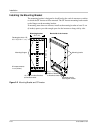
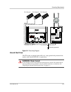
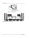
A DC grounding electrode conductor may be required by the Authority Having
Jurisdiction (AHJ). Use the GT Inverter ground bar for this connection (see
Figure 3-2 on page 3–3).
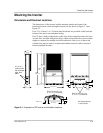
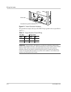
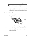
Two ¼-inch (7 mm) knockouts in the bottom of the wiring box are intended for
routing the ground conductors to the ground bar. See Figure 3-1.
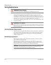
CAUTION: Equipment damage
Provide adequate clearance for grounding wires inside the GT Inverter wiring box. Ensure
that the bare copper grounding wire is more than ½ inch clear of the DC/AC interconnect
circuit board.