


Communications Wiring for Multiple Inverters
975-0320-01-01 3–15
Guidelines for Routing the Network Cables
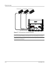
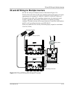
Connecting Network Cable Between Multiple Inverters
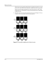
The following procedure is illustrated in Figure 3-11. The procedure assumes only
two inverters are connected. However, there can be up to ten inverters wired in
this configuration.
To provide communication between multiple inverters:
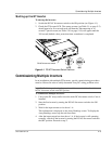
1. Remove the wiring/disconnect box cover from each unit.
2. Connect the network cable to any RJ45 port in Inverter #1.
3. Route the cable along the top of the insulation barrier and through a side
conduit hole to Inverter #2.
4. Connect the network cable to any RJ45 port in Inverter #2.
5. For more than two inverters, continue connecting cable as described above.
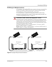
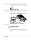
6. Insert male network terminators into the empty RJ45 ports in the inverters at
the beginning and end of the network. There should be no empty RJ45 ports in
any of the inverters.
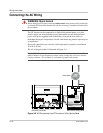
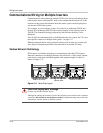
Communications Wiring for Monitoring a Single Inverter
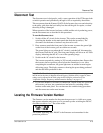
You can view GT Inverter operational data on a personal computer using the
Xantrex GT Solar Inverter Viewer (“GT-View”), which you can download free of
charge at www.xantrex.com.
To use GT-View, you must connect your computer’s serial port to the GT Inverter
RS-232 port (see Figure 3-13).
:
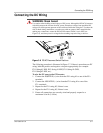
WARNING: Shock hazard
Do not route the network cables in the same conduit or panel as the AC and DC power
cabling. The cables should run on top of the insulation barrier inside the wiring/disconnect
box and out the side conduit hole, avoiding any contact with the AC and DC wiring.
CAUTION: Unpredictable device behavior
Do not connect one end of the network to the other to make a ring or loop.
WARNING: Shock hazard
Before opening the GT Inverter wiring/disconnect box, turn OFF the breaker switches
connected to the GT Inverter AC output, and turn the DC/AC Disconnect switch to the
OFF position. Hazardous voltage will still be present on the DC input (PV) terminals
located under the clear plastic insulation barrier. Do not remove the insulation barrier
during this procedure. To reduce the risk of shock, cover the array with an opaque (dark)
material.