


Monitoring the Inverter
5–2 975-0320-01-01
Viewing more
information
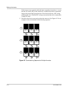
Additional screens of information about the performance of the GT Inverter can be
displayed by tapping the Xantrex logo on the inverter front panel. This causes the
LCD to cycle through a series of information screens in Normal Operation,
Offline or Fault modes. These are described in detail in the following section,
“Front Panel Display Screens and What They Mean”.
Front Panel Display Screens and What They Mean
The front panel display shows different message screens during different modes of
operation (Startup, Normal, Offline, and Fault). All single units display a basic set
of message screens; multiple unit systems display additional screens in Normal
Operation and Offline modes.
In addition there are Special message screens that may appear in any operational
mode. All these message screens are described in more detail in the following
tables.
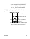
Startup Mode
During startup, the GT Inverter displays several message screens on its front panel
LCD. These screens appear in the following order (Table 5-1).
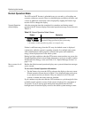
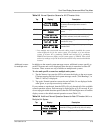
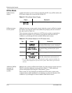
Table 5-1
Startup Screens on GT Inverter Front Panel Display
Display Duration Description
Power 5000W
Region NA-240V
5 seconds Startup message 1: Maximum output power and
Region-nominal output voltage
Flash = 03.00
..ROM = 03.00
5 seconds Startup message 2: Model and revision numbers
for Flash and ROM memory on the GT Inverter.
The ROM revision number applies to the
protection processor.
Vh= 261V
Clr t < 1.00s
3 seconds Vh: phase-to-phase (rms) high threshold voltage
setting, the threshold at which the inverter
disconnects itself from the power grid when
abnormally high phase-to-phase AC voltage is
detected.*
Clr t: clear time.†
Vl= 214V
Clr t < 2.00s
3 seconds Vl: phase-to-phase (rms) low threshold voltage
setting, the threshold at which the inverter
disconnects itself from the power grid when
abnormally low phase-to-phase AC voltage is
detected.
Clr t: clear time.