


Connecting the DC Wiring
975-0320-01-01 3–7
Connecting the DC Wiring
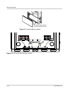
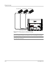
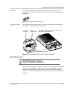
The following procedure is illustrated in Figure 3-7. If there is more than one PV
string, label the positive and negative wire pairs appropriately (for example:
PV1-String #1 POS, PV1-String #1 NEG, PV1-String #1 GND,
PV1-String #2 POS, etc.).
To wire the PV array to the GT Inverter:
1. Connect the POSITIVE (+) wire from the PV1 string #1 to one of the PV+
terminals.
2. Connect the NEGATIVE (–) wire from the PV1 string #1 to one of the
PV– terminals.
3. Repeat for the PV1 string #2, if there is one.
4. Repeat for the PV1 string #3, if there is one.
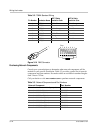
5. Ensure all connections are correctly wired and properly torqued to a
maximum 16 in-lb (1.8 Nm).
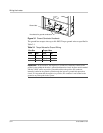
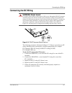
WARNING: Shock hazard
Use caution when working around sources of DC power. Although the DC/AC disconnect
switch disconnects the inverter from DC power, hazardous voltages from paralleled PV
strings will still be present upstream of the switch and inside the wiring box. To reduce the
risk of shock during installation, cover the array with an opaque (dark) material before
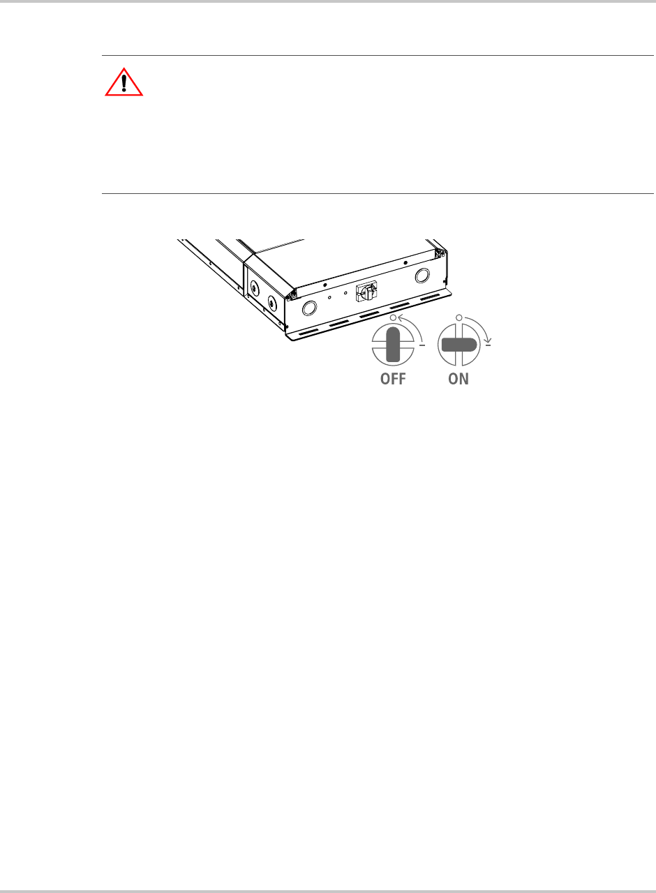
making any connections, ensure the DC/AC Disconnect Switch is set to OFF (see
Figure 3-6), and always test for voltage before touching exposed wiring or devices.
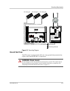
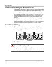
Figure 3-6
DC/AC Disconnect Switch Positions