


Starting the Inverter
4–2 975-0320-01-01
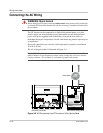
Checking the PV Array DC Voltage
To check the PV array DC voltage:
1. Uncover the PV arrays and expose them to full sunlight. The sunlight must be
intense enough to produce the required output voltage.
2. Measure the PV array open circuit DC voltage across the DC positive (+) and
negative (–) terminals. This voltage must be greater than 150 volts DC (to
energize the electronics) and less than 600 volts DC (to prevent damage to the
inverter).
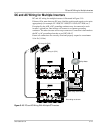
Checking the AC Utility Voltage
To check the AC utility voltage:
1. Switch on the main and inverter breakers in the main electrical service panel.
2. Using an AC voltmeter, measure the AC open circuit utility voltage between
L1 and L2. Ensure this voltage is at approximately the nominal value. The
inverter operates with a line-to-line voltage (L1 to L2) range around the
nominal value.
See “Electrical Specifications”, “Output” on page A–2 for the utility voltage
operating range for your GT Inverter model.
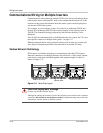
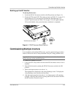
Replacing the Wiring/Disconnect Box Cover
After performing the voltage checks, replace all covers that were removed during
installation and startup.
To replace the wiring/disconnect box cover:
1. Ensure the clear plastic insulating barrier is properly positioned in the wiring
box.
2. Place the cover in position on the wiring box, being careful not to pinch any
wires inside.
3. Ensure that the two screw holes in the bottom of the wiring box cover are
aligned with the corresponding holes in the bottom of the wiring box.
4. Replace the two screws removed when the cover was removed (see
“Accessing the Wiring Terminals” on page 3–5), and tighten securely.
WARNING: Shock hazard
Before reattaching covers, turn OFF the breaker switches in the main utility service panel
and the DC/AC Disconnect switch on the GT Inverter.