


Installation
2–24 975-0082-01-01
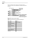
If your generator battery does not have the required voltage, any 12V or
24V power source will suit this purpose. If an alternate power source is
used, the negative of the power source must be connect to the other
contact of the switch.
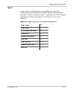
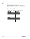
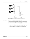
Multiple control panels or simple contact closures can be wired to the
external manual on/off inputs. The Auto Gen Start detects if any of the
contacts close and will change its operating mode to External Manual On
or External Manual Off (for more information, see “AGS Mode” on
page 3–9). The Auto Gen Start turns the generator on or off according to
these inputs and the resulting operating mode change.
Unlike the Manual On or Manual Off operating modes you can enter by
using the System Control Panel, the External Manual On and External
Manual Off states are not affected by maximum generator run time (see
“Max Run Time” on page 3–29).
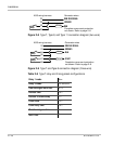
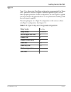
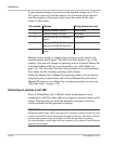
Connecting an external on/off LED
Wires 9 (White/Blue) and 11 (Black) on the wiring harness can be
connected to an LED or other light to accompany a remote external on/off
switch. This light turns on when the generator run signal is active to
visually indicate that the generator is running.
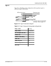
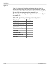
Wire number Function Wiring harness wire color
7 External manual on input White/Green
8 External manual off input White/Red
9 External On/Off LED Indicator
output
White/Blue
10 Constant 12/24 V B+ for
External On/Off/LED Indicator
Red
11 External On/Off/LED Indicator
return
Black
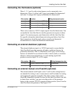
Important::
With some generators, the generator run signal becomes active
during the preheat stage, before the generator is actually running. In this case, the
external on/off LED (and the Generator On light on the Auto Gen Start) will turn
on during the preheat stage and remain on when the generator is running.
For some generators, these lights will also remain on for a period of time after the
generator has stopped.