


Rev. B
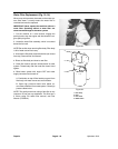
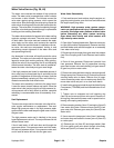
Plunger Seal Replacement
(See illustration on previous page)
NOTE: Check valves must be in good condition for this
procedure to work correctly.
1. Fill pump head outlet cavity with water, then use two
capscrews to temporarily install Pump Seal Outlet Cov
-
er (TOR4014) onto outlet port of pump head. Check
valves must be installed.
2. Position pump head on a SOLID workbench or in a
vise keeping displacement rod openings pointing up
-
wards.
3. Fill plunger openings with water. Insert Pump Seal Ex-
traction Tool (TOR4013) into each water filled cavity.
WEAR SAFETY GLASSES. Quickly, strike the extrac
-
tion tool with a large hammer or mallet. The seal assem-
bly and brass retainer should move about 1/4” out of the
cylinder head. If seal does not move, add more water
and try again. NOTE: If seal does not move after a few
attempts, try using heavy oil or grease instead of water.
4. Remove all seals from pump head and remove outlet
cover tool. Discard back–up ring (Item 6), packing vee
(Item 5) and seal support (Item 4). Inspect brass seal re
-
tainer (Item 2) for wear and replace if worn. If brass seal
retainer can be reused, remove and replace U–cup seal
(Item 3) and O–ring seal (Item1).
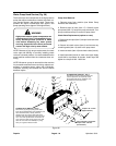
NOTE: Apply clean grease to each seal before installing
in steps 5 – 9.
5. Insert back–up ring (Item 6), flat side first, into each
pump head cavity.
6. Insert packing vee (Item 5) into Installation Guide
(TOR4010) making sure that “V“ will mate with back–up
ring (Item6).
7. Insert Installation Guide into cylinder head cavity and
use Insertion Mandril (TOR4011) to completely install
the seal.
8. Insert seal support (Item 4) into Installation Guide
(TOR4010) making sure “V“ groove will mate with high
pressure seal. Insert Installation Guide into cylinder
head cavity and use Insertion Mandril (TOR4011) to
completely install seal support. This seal support fits
tightly in the bore.
9. Install new U–cup seal (Item 3) and O–ring seal
(Item1) into seal retainer (Item 2). Install seal retainer
into pump head cavity. Use a soft face (plastic) hammer
or arbor press to completely insert backup ring into
pump head.
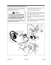
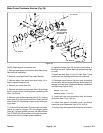
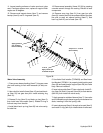
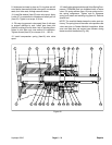
Plunger Sleeve Replacement
(Model 09800)
(see Figure 38 on next page)
The plunger sleeves are installed on, and sealed to
stainless steel plunger rods. This assembly is inserted
through a special high pressure seal in the pump head.
During pump servicing, a complete repair kit should be
installed.
1. Remove plunger sleeves (Item 26) from crankcase
plunger rods (Item 9) by loosening and removing plung
-
er bolt assemblies (Item 30). The plunger sleeves can
be gently pulled forward for inspection or replacement.
Remove large washer (Item 25) from rear of plunger rod.
2. Remove O–Ring (Item 29) and PTFE seal (Item 28)
on plunger bolt assembly (Item 30). Install new greased
O–ring (Item 28) next to head on bolt, then install PTFE
ring (Item 28).
3. Install new large washer (Item 25), then new plungers
(Item26), onto plunger rods.
4. Apply Loctite 271 or equivalent to threads of plunger
bolts, then install assemblies onto plunger rods. Torque
plunger bolts to 10 ft–lbs.
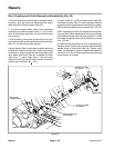
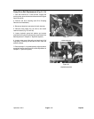
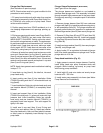
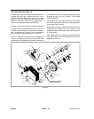
Pump Head Installation (Fig. 37)
1. Apply grease to ceramic plunger sleeves. Carefully
install pump head onto pump crankcase studs and
plungers. While installing, tap evenly on pump head
while turning pump crankshaft.
2. Install eight (8) nuts onto studs and evenly torque
locknuts to 25 – 33 ft–lbs.
3. Install water pump assembly into frame (see Water
Pump Removal and Installation).
Figure 37
Hydroject 3010
Page 6 – 25
Repairs