


24
23
22
21
20
19
16
18
5
26
27
28
29
25
6
7
8
9
10
35
36
37
38
39
11
12
13
14
15
17
1
2
3
4
40
34
33 31 32
30
4
3
2
1
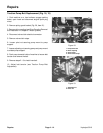
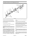
Figure 25
Disassembly of Hydraulic Pump
1. Before performing major repairs on the pump, remove
external components as described in previous proce-
dures. These include the following:
Shaft Seals
Charge Check Valves
Bypass Valve
Charge Pump
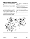
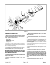
2. Lay pump on its side. Use a 6 mm internal hex wrench
to remove the four (4) screws (Item 30) which retain end
cap to variable pump housing.
3. Internal springs will separate end cap from housing.
Remove end cap (Item 31) from housing (Item 18).
IMPORTANT: Pump cylinder block (Item 7) will stick
to surface of end cap. Be careful to prevent damage
to end cap and cylinder block.
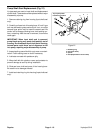
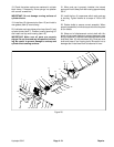
4. Remove gasket (Item 6) and two (2) alignment pins
(Item 15) from housing.
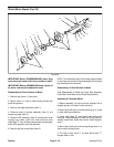
5. Remove cylinder block kit (Item 7) from shaft
(Item 19).
6. Remove cylinder block spring (Item 8) and washer
(Item 9) from shaft.
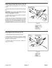
7. Remove swashplate assembly (Item 25) from hous-
ing.
8. Remove thrust plate (Item 11) from swashplate. The
bearing guide is pressed into the swashplate and is
usually not removed. The inner thrust washer is retained
by the bearing guide.
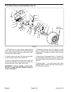
9. Remove slot guide block (Item 13) from displacement
control shaft (Item 12).
10. Remove swashplate cradle bearings (Item 14) from
housing.
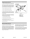
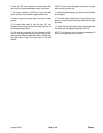
11. Remove input shaft seal retaining ring (Item 24).
12. Carefully pull input shaft seal (Item 23) out of hous-
ing bore. A hook may be used to pry seal out, or a slide
hammer type puller may be used to remove the seal. Be
careful not to damage housing bore, shaft sealing sur-
face, or bearing. After seal is removed it cannot be used
again.
13. Remove bearing spacer washer (Item 22).
Hydroject 3010 Page 4 - 19 Repairs