


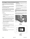
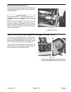
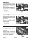


Pump Clutch (Fig. 21)
To test the pump clutch, disconnect the wire connector
and connect a continuity tester or ohm meter across the
terminals of the clutch wire connector. There should be
continuity across the terminals of the clutch connector.
Resistance measured through the clutch coil should be
approximately 3 ohms.
The clutch can also be tested by connecting a 12 VDC
battery across the clutch connector terminals. The
clutch should engage as 12 VDC is connected to the
clutch connector terminals.
Clutch coil resistance:
3.79 Ohms + 5% at 20
o
C (68
o
F)
Figure 21
1. Pump clutch
1
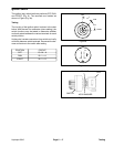
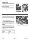
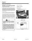
Valve Clutch (Fig. 22)
To test the valve clutch, disconnect the wire connector
and connect a continuity tester or ohm meter across the
terminals of the clutch wire connector. There should be
continuity across the terminals of the clutch connector.
Resistance measured through the clutch coil should be
approximately 3 ohms.
The clutch can also be tested by connecting a 12 VDC
battery across the clutch connector terminals. The
clutch should engage as 12 VDC is connected to the
clutch connector terminals.
Clutch coil resistance:
3.5 Ohms
+ 5% at 20
o
C (68
o
F)
Figure 22
1. Valve clutch
1
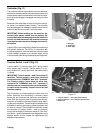
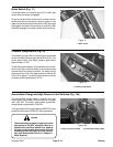
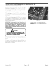
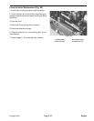
Circuit Breaker and Fusible Link (Fig. 23)
The electrical system is protected by a 20 AMP circuit
breaker with reset button and a fusible link.
To test the circuit breaker, check for continuity between
the two terminals.
The fusible link is located in the control panel wiring
harness between the circuit breaker and and starter B+
terminal. To test the fusible link, check for continuity
between terminals J22 and J23 of the control panel
wiring harness (see Schematic and Control Panel Wir-
ing Harness in Chapter 8 - Electrical Diagrams).
Figure 23
1
1. Circuit breaker
Hydroject 3010 Page 5 - 23 Testing