


1
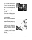
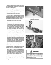
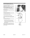
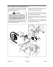
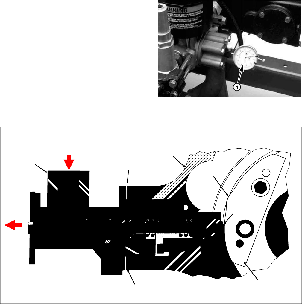
5. Remove test cap from manifold feeder and install
Valve Lift Indicator (TOR4007) into this opening. Make
sure dial indicator contacts top of water valve, then zero
out dial indicator.
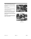
6. Rotate coupling, moving cam toward cam follower.
Continue to rotate until cam follower is on lead-in portion
of cam, approximately one inch (slightly less than 1/2
turn of coupler) from cam lobe. If dial indicator shows
no lifting of valve, loosen four (4) capscrews holding
gear case to valve body. Remove one shim from both
front and rear, then tighten capscrews. Repeat this
procedure until some opening of valve occurs on lead-in
portion to make sure cam follower touches cam.
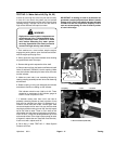
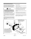
7. Zero dial indicator again with cam follower completely
off the cam. Rotate coupling, moving cam toward cam
follower and continue to rotate until cam follower is on
lead-in portion of cam, approximately one inch from cam
lobe. Record amount of valve lift.
IMPORTANT: Make sure shims on both front and
rear side are the same thickness. Using different
thicknesses can cause gear case damage.
8. Add shims, equal to or greater by 0.002 inch, to
amount measured. For example, if 0.015 is measured
while follower is on lead-in portion of cam, add a 0.015
shim. If 0.009 is measured, add 0.010 shim (two 0.005
shims) and retighten capscrews.
NOTE: If more than a multiple of 0.005 shims are
required, it is recommended that procedure be done in
two steps - for example if 0.023 is indicated, add 0.02
shim (four 0.005 shims) first, then repeat procedure.
IMPORTANT: Clearances greater than 0.002 in. will
cause high contact stresses and rapid cam wear.
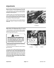
9. Check proper function of cam by again zeroing dial
indicator with cam away from cam follower. Rotate
coupling, moving cam toward cam follower and continue
to rotate until cam follower is on lead-in portion of cam,
approximately one inch from cam lobe. There should be
no movement of dial indicator on lead-in portion of cam.
Continue to rotate over cam lobe. Lift should measure
0.10
+0.002
/
–0.004
in. (with new cam). Continue to rotate
on lead-out portion. The dial indicator should read zero
for entire lead-out portion.
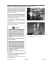
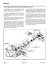
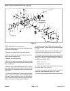
Figure 28
1. Valve lift indicator (TOR4007)
Gear case
Shims
Cam follower
(on lead-in portion of cam)
Cam
Shims
Water valve
housing
Cam lobe
Water (4000 - 5000 PSI
operating pressure)
Figure 29
HydroJect 3010 Page 6 - 19 Adjustments