


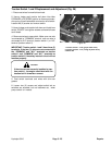

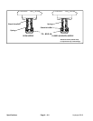

Traction Switch 1 and 2 Replacement and Adjustment (Fig. 26)
1. Disconnect wires from switch terminals.
2. Have a helper push traction bail down into either
FORWARD or REVERSE position or disconnect exten-
sion spring; this will take switch arm tension off of switch.
Loosen two (2) screws and remove switch.
3. Have a helper push traction bail down and Install new
switch. DO NOT over-tighten screws as the switch case
could break.
4. Reconnect wires to new switch. Make sure one wire
is connected to “COMMON” terminal, and one wire is
connected to N.O. terminal (traction switch 1) or N.C.
terminal (traction switch 2).
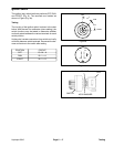
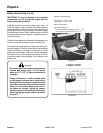
Figure 26
IMPORTANT: Traction switch 1 and 2 have three (3)
1. Traction switch 1 – N.O. (gray & black wires)
terminals. If the two (2) wires are not connected to
2. Traction switch 2 – N.C. (orange & yellow wires)
3. Switch tab
the “COMMON” and “N.O.” terminals on traction
switch 1 and “COMMON” and “N.C.” terminals on
traction switch 2, the safety interlock circuit will not
function properly.
1
3
2
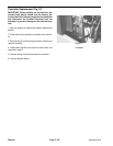
traction bail in forward or reverse.
CAUTION
If the wires are not correctly installed to trac-
tion switch 1, the engine could start with the
5. Coat switch terminals and wires with skin-over
grease.
6. Loosen two (2) screws and adjust switch tab so
switches are actuated, but not bottomed out, when
pump control is in neutral.
Hydroject 3010 Page 5 - 25 Repairs